PocketRxTx version 4 User Guide
Revision 5
Transceiver & WebSDR remote control for Android
Dan Toma - YO3GGX - yo3ggx@gmail.com
Please do not give negative feedback in the Google Play Store before contacting me through the application forum to clarify any issues with the application. I promise to answer you ASAP. PocketRxTx is available as a “LITE” version (Free) or as a “PRO” version, with some extra features. Please install the Lite version first to check if it is useful for you and only if so, consider getting the PRO version.
Selecting WebSDR client mode at first start
Selecting a Direct CAT mode at first start
Application graphical interface
Startup page in WebSDR client mode
Startup page in Direct CAT mode
Application GUI on different Android devices
WebSDR mode startup screen formats
WebSDR mode radio screen formats
Direct CAT mode startup screen formats
Direct CAT mode radio screen format
EEPROM COMMANDS (only for Yaesu FT8x7 radios)
Operating the application in WebSDR mode.
WebSDR server’s repository (LEGACY mode)
WebSDR server’s repository (MAP mode)
Tuning using the waterfall/spectrum
Adjusting waterfall brightness or spectrum minimum level
Operating the application in Direct CAT mode.
Transmitting a CW message by direct text entry
Transmitting a CW message by recalling a pre-stored message
Creating a voice message using Text-to-speech engine
Transmitting a voice message by entering text
Transmitting a voice message by recalling a pre-stored voice message
Deleting a recorded voice message
Transceiver configuration files
The header – general info about the radio.
Using macros in the radio configuration file
Using the application in server mode
Using the application on devices with a small screen (ex. Network Radios)
Returning to the call before saving call info
Discarding current call record
Sending Call Log file by email
Using external third-party devices with Pocket RxTx
ABBREE Bluetooth Handheld Speaker Mic
Mini Bluetooth Remote Photo Shutter
Server application (pRxTxServer4)
Downloading server application
Running packaged server application
Running the app using the JAR file
Operating the Full variant – GUI based (psrv4full)
Creating an application profile
Operating the MINI variant – Console based (psrvmini4)
Introduction
PocketRxTx is an Android only application used to remotely control different Amateur Radio receivers or transceivers. You can connect through the Internet to a WebSDR server or via Bluetooth, USB/Serial or network connection to your own Amateur Radio transceiver.
Features
The current version of the application has the following main features:
· Works on any Android device, including smartphones and tablets, with a minimum screen resolution of 800x480 pixels and running Android version 5.1 or higher. Was tested up to Android 15.
· Can be used in compact mode on smaller resolution systems (like network radios), even at 240x320 resolution.
· Works in both portrait and landscape modes.
· Mic DSP with 4 bands audio compressor (PRO version only).
· FT8 decoding with table or map display (PRO version only).
· Configuration files can be exported to a PC/Mac and imported from a PC/Mac through the pRxTxSrv4 desktop application (available for free on my web site).
· The application can be used in server mode (PRO version only). IN this way you can use a cheap old Android smartphone as a server instead of pRxTxSrv4 desktop application.
· Audio Loop function allows you to check the full audio path (locally or over the network), even without connecting to a radio. It works like Echo mode in Echolink.
· Sticky PTT feature (block PTT to ON) and clear it by pressing PTT again (PRO version only).
· Connection over the network is done using a single TCP port for CAT, audio and app control.
· Audio and CAT commands are transferred in the background.
· Tuning is possible:
· through the rotary knob.
· by directly entering the frequency from a numeric keypad (in MHz).
· using Up/Down buttons to change the frequency with a preset step value for (+ and -), which can be dependent upon the selected band.
· by directly selecting a specific digit and changing the value through the knob or Up/Down buttons (PRO version only).
· select digit to adjust (PRO version only, when displaying in 7-segments mode).
· 99 pre-set channels can store all currently set parameters in 99 memories. Lite version is limited to 16 memories.
· Frequency display can use a 7-segment mode (PRO version only), allowing independent digit selection for tuning.
· A special mode, named Mixed Mode and available in PRO version only, allows you to transmit using your own transceiver and receive using a WebSDR server. Parameters are automatically synchronized, and you can switch in real-time between radio and WebSDR audio during the call.
· You have the possibility to set frequency offset in WebSDR mode, to compensate for the WebSDR servers that are not well calibrated.
· The ON/OFF button connects or disconnects the application from the remote server or locally connected transceiver.
· Bands may be selected from the list of valid ones for the selected transceiver.
· Operating mode (AM/ LSB/USB/CW/ etc.) may be selected from the application
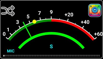
· The Signal strength in receive and SWR/PWR/ALC/MOD/VLT in transmit are displayed using a bargraph or an analog style meter (available in PRO version only). In PWR meter mode, the scale is automatically adjusted based on the maximum power available on the selected transceiver.
· You may set the application font size according to your preference, using an intuitive graphical interface.
· A UTC clock is included in the interface.
· Call logging is available inside the application, with QRZ database query support. In Lite version, call logging is possible only in WebSDR client mode.
· Selectable tuning band stops by IARU region.
· Can connect to the transceiver over Bluetooth, USB/Serial or Network.
· You can select audio device to be used for Rx and for Tx (only on Android 6.0 and up).
· USB/Serial multi-port interface support. With PTT over CAT, RTS or DTR (user selectable), selectable comms port (e.g. Yaesu FT-991 USB or SCU-17 interface).
· Network connections use secure authentication (using PKI).
· When using a network connection Bi-directional audio support is available without the need for external applications.
· All configurations are stored in profiles, to allow operation of different radios without having to re-enter the configuration data each time you switch between them. Maximum number of profiles is limited to 1 in LITE version (unlimited numbers in PRO version).
· Radio model support is controlled through a textmode configuration file and can be edited by the user directly from the application.
· You get permanent feedback for all defined radio parameters (if reading parameters over CAT is allowed by the selected radio), so you can use the app as a bigger display for your radio and still operate the radio from the local buttons.
· To edit the textmode configuration file on a PC/Mac you can Import/export between the Android device and a computer through the pRxTxSrv4 desktop app, which may also be used for configuration backup purposes.
· A video guide is now available from the HELP menu.
· Use a mouse wheel for tuning, left button for PTT and right button for mute (PRO version only).
Specific functions in SDR Receiver mode:
· PocketRxTx can connect to any one in a list of WebSDR servers. New servers can be added to the list in the future without requiring any application update.
· Receive mode (AM/USB/LSB/CW/FM), IF bandwidth (Normal/Narrow/Wide), and Band/frequency can be selected through the application.
· The application has a waterfall/spectrum display with a zoom of up to 64x (for RTLSDR based servers).
· By using the user’s and the WebSDR server’s geographic coordinates the distance between them is displayed (more details are available if the Location Service in the Android device is activated).
· The application contains a Mute button.
· For SWLs call logging support with QRZ database query is available.
Application limitations
· Because of the Android subsystem limitations, audio when connected over USB or Bluetooth to your radio is currently supported in only one way (from radio to the Android device. Use your radio microphone or a wireless microphone (if available for your radio) for Tx.
· Only one USB audio device is supported. Always the last connected one will be recognized by the application.
· Only Bluetooth audio devices supporting SCO and (eventually) A2DP are supported. BLE audio devices are not currently supported.
· Because of Android limitations, you cannot use SCO for audio input and A2DP for audio output. SCO must be selected for both. If headset must be used for both Rx and Tx, select SCO. If used only for Rx (WebSDR or another receiver), use A2DP, for best audio quality.
· Several tests were performed. However, without having access to every possible Android device and every CAT enabled rig, testing cannot be comprehensive. This means that the application may have bugs or may crash for apparently no reason. With your help as users, issues can be solved one by one and new features are added. This is the model used so far to advance the development of the product, and it is hoped that this co-working method can continue.
· Note that the network connection encryption is used only for the initial authentication (login) to the server, after that all the traffic is unencrypted, for both CAT and audio. If security is required, the use of a VPN or tunneling protocol is recommended.
WARNING!!!
Use this application at your own risk. When using a network connection, it is possible that your PC may be accessible from the Internet. It is your responsibility to address this risk if you consider it to be an issue. One possible approach may be to use some kind of VPN (e.g. PPTP). The application only provides secure login authentication, no data encryption. A full encryption option is planned to be added in the future. If you are not comfortable with this situation and you are not able to use any kind of VPN, then only use the network link from the App over your own internal LAN.
This application does not send any “dangerous” data to the transceiver however as the protocol used by Yaesu for FT-8x7 CAT control does not use any error correction mechanism, it is possible (in some unlikely situations) that unexpected results may occur such as a software crash on the transceiver (requiring to power cycle to rectify it). In a worst-case scenario a complete wipe of all EEPROM data, including configuration, software calibration/alignment and memories is theoretically possible. As all CAT commands used by PocketRxTx are user customizable by just editing a text file, extra caution must be exercised when changing the radio configuration textmode file.
In the case of Yaesu FT8x7 equipment it is highly recommended to save your transceiver settings using a program such as “FT 817 Commander” (you can use Google search to find it) before starting to use this application. As a minimum save all “soft calibration” settings, plus any other information stored in your radio before using this application.
I cannot be held responsible for any damage caused to your Android device, your transceiver or your PC… You have been warned!
Asking for support
Because of the high diversity of Android devices on the market, the broad range of versions support (from Android 5.1 to Android 16) and impossibility to test in advance all possible use cases, some specific features may not function as expected. Please do not give negative feedback in Google Play Store before reporting your issue with the application.
The users of the PRO version can ask for support or report bugs directly from the application HELP menu, as described here.
NOTE: For the users of the LITE version, support is available only through the application forum, accessible from the HELP menu as described here.
I will do my best to answer as soon as possible to all support requests. Thank you for your understanding
Starting the application
You can install the application directly from the Google Play Store (search for “Pocket RxTx”).
NOTE: If you are running the application on Android 6.0 and above, no special permissions are generally required to run it. Only if specific permission is required to be provided to access some application features, will you be asked to grant permission. If you deny this permission, just that feature will not be available. On Android version 5.1, permissions required by all the application’s features will be requested during the application installation.
After you install the application, a new icon like in the images below will be available (depending on the version):
|
LITE |
PRO |
BETA |
|
|
|
|


Tap the icon to launch the PocketRxTx application.
NOTE: Beta versions, when available, are distributed through Google Play Store Internal Testing mechanism. You must be registered with the internal test team to be able to download a beta version.
When you start the application for the first time after a fresh installation, you will be asked to allow Pocket RxTx to send notifications. In fact, this means that if you allow it, the app will be shown in the notifications list when it is running, even in the background. By tapping the notification, you bring the app in foreground.
Be aware that this permission may be mandatory on some devices to allow the application to run in the background.
During the first start of the application or after an application reset (see later), you will be prompted to create a new application profile. Enter the name for the profile. You can use both lower and upper cases, which will be preserved. It is recommended to use a name that will contain the radio or WebSDR server to be used in this profile and connection mode, to be easily found in the list if you define multiple profiles.
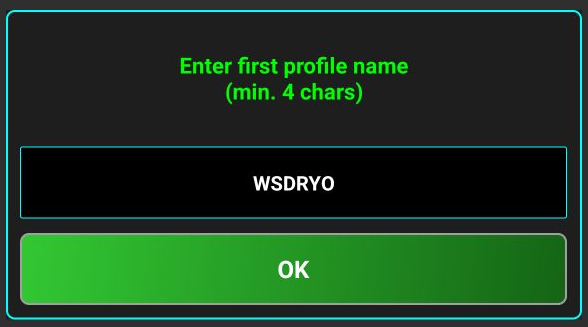
Press OK.
You will now be prompted to enter your callsign. If you are not a licensed HAM radio operator, enter any text/nickname. This will be used to mark your presence when connected to a WebSDR server, to log calls, etc.

You can enter the callsign in lower or uppercase, but it will be automatically converted to uppercase. Then press OK.
NOTE: If you don’t have a callsign, use any string with minimum 8 characters, containing letters and numbers. This will be used as an alias/nickname to show your presence on a WebSDR server.
Next you will be asked to provide your grid (maiden) locator, using between 4 and 10 chars, according to the precision you need.
Locator can be automatically detected. For this, tap on FIND button. You will be asked for Location permission.

It is enough to select “Only this time”, as this permission will not be required anymore during normal application operation. The locator field will be automatically filled with your high precision locator (10 characters).
If you want, you can keep less characters (for smaller precision), but not less than 4 characters. Usually, 6 characters are used. If you don’t want to provide Location permission, you can enter the locator manually. The entered value must be a valid locator, otherwise you cannot go further.
NOTE: All location data is stored only locally, on your device. You can change own locator later, by long pressing on the application name in the startup page, as described here.
When ready, tap OK.
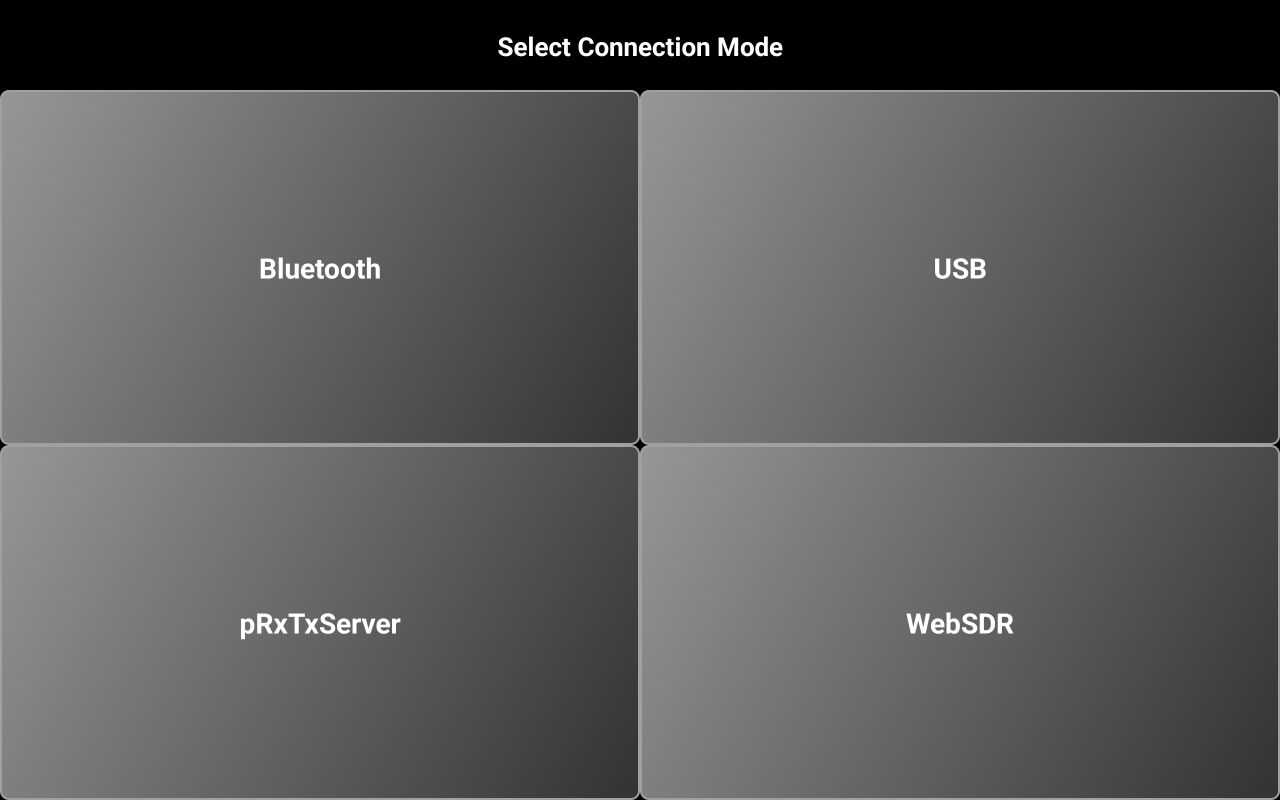
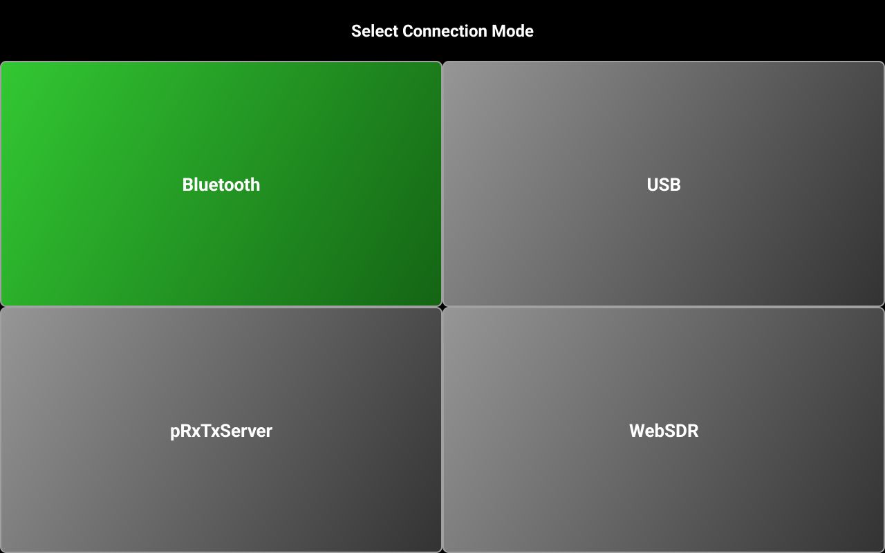
Next you will be asked to select connection mode.

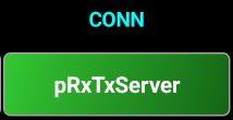
Select pRxTxServer if you want to connect to pRxTxSrv4 desktop application or to another instance of Pocket RxTx4 running in server mode. The other 3 are self-explanatory. Tap on your selection. Let’s say you select WebSDR.
Selecting WebSDR client mode at first start
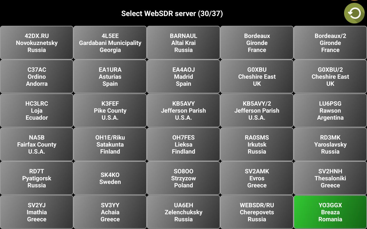
Let’s consider that you selected WebSDR. In the PRO version, you will ask to choose selection mode for the WebSDR servers.

LEGACY means the classic selection mode, from a selection panel. MAP is a new mode, where you can select the WebSDR server on a world map. Let’s consider you select LEGACY. The application will start to check for availability all the WebSDR servers from the central repository, presenting the search status at the bottom of the screen.
![]()
Tap on the server you want to connect to.
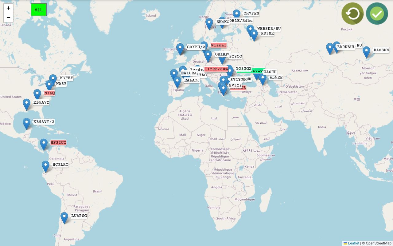
If you use the PRO version and select MAP in the previous screen, available servers will be shown on the world map.
You can use pinch and zoom to get more details in a specific area. Then tap the server you want to select. The map will auto zoom in to maximize the area, and a red line will be drawn between your location and that server, with the direct distance between the two points marked on the line.
For the selected server, the list of available bands is displayed in a green box.
Click on the Confirm icon in the top right part of the screen.
The application startup page will be displayed for WebSDR client mode.
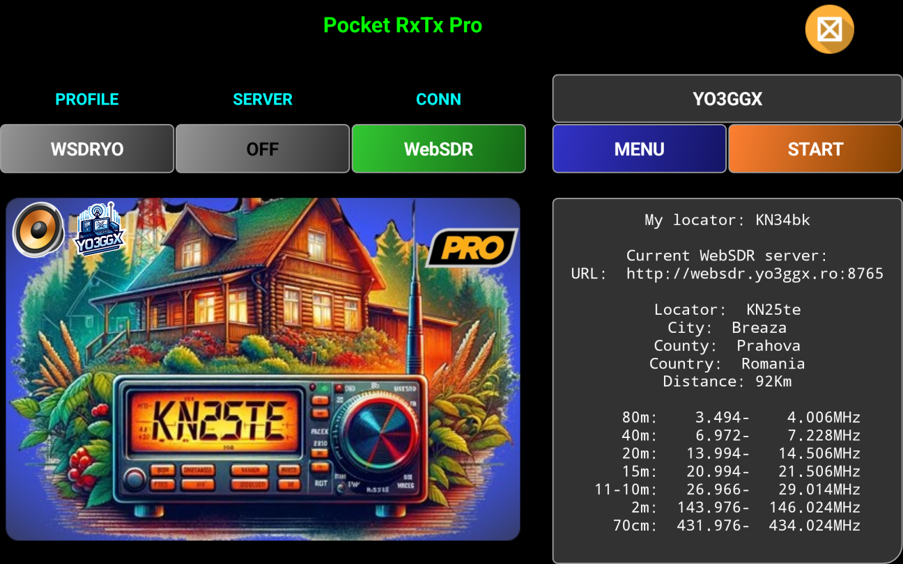
More about how to operate WebSDR client mode here.
Selecting a Direct CAT mode at first start
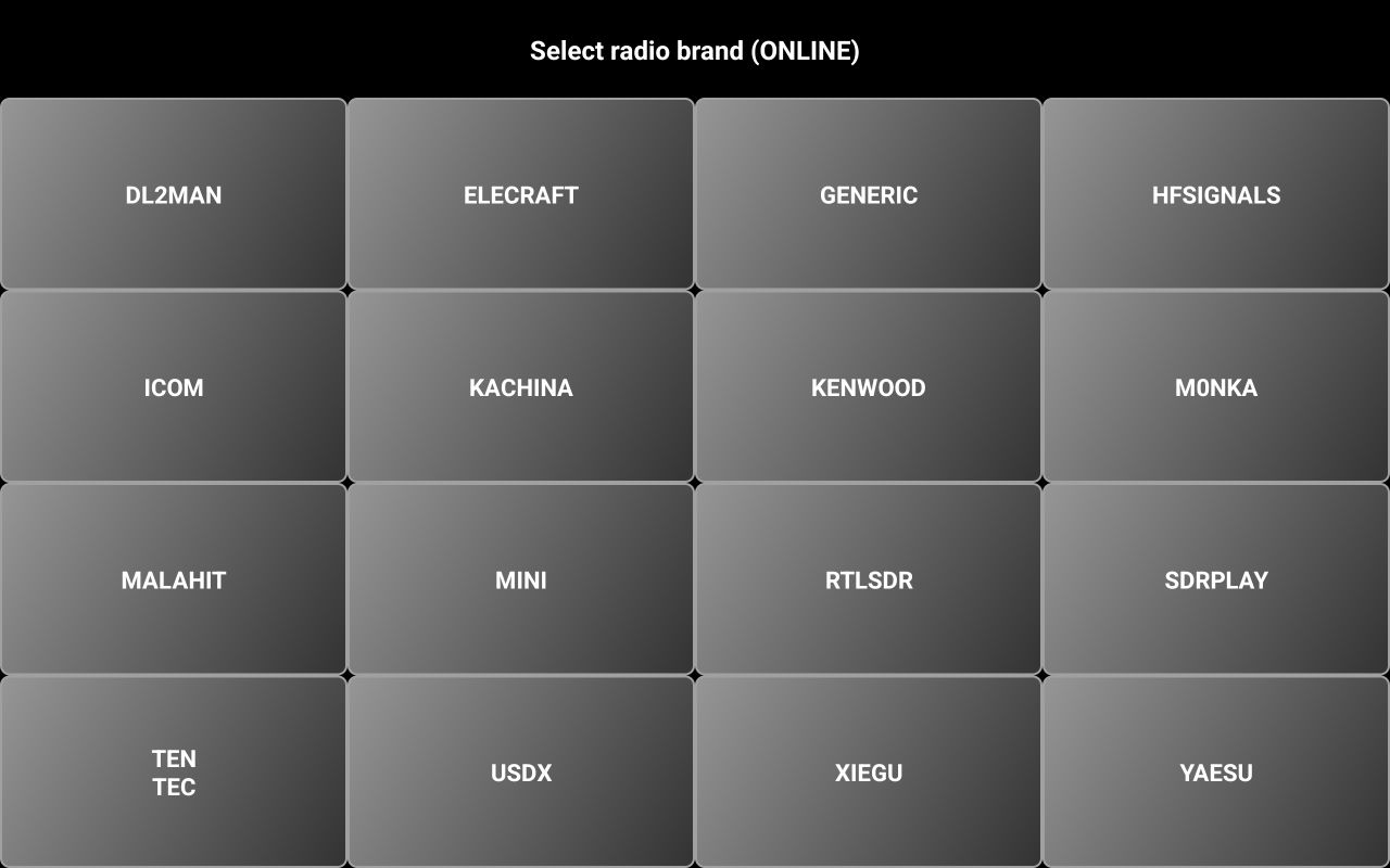
If you select one of the other 3 connection options, you will be prompted to select your radio from a list.
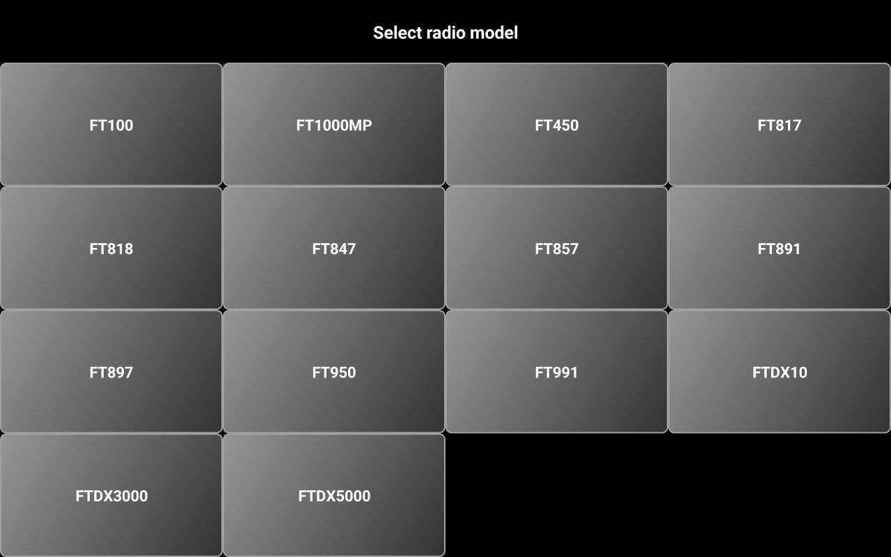
First a selection panel with all the brands supported is displayed.

Select desired the brand of the radio you want to control. Let’s consider YAESU. Now select the radio model. Let’s consider FT450.

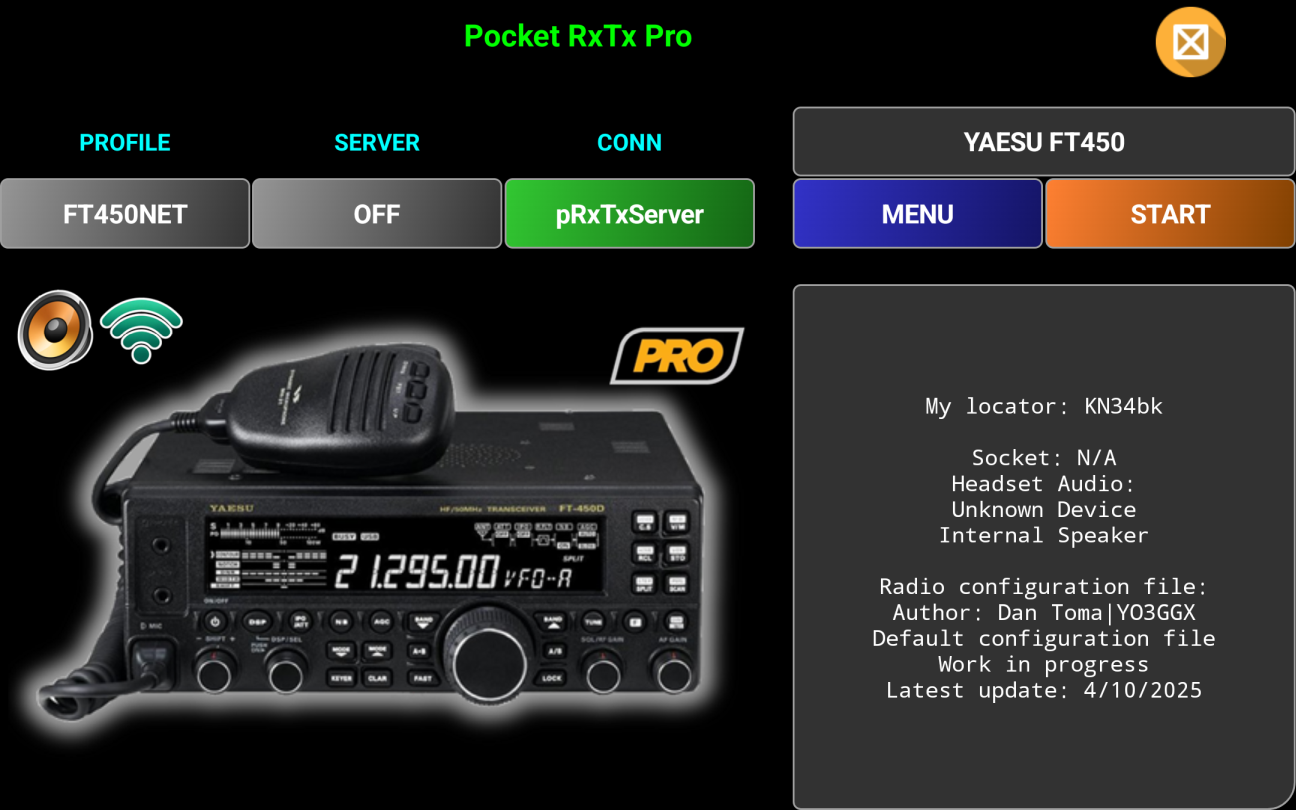
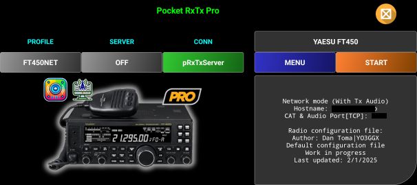
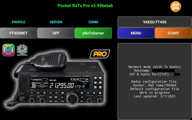
The application startup page will be displayed (for CAT mode).
More about how to operate Direct CAT mode here.
Exiting the application.
To exit
the application at any time, click on the ![]() (Exit)
icon in the top right corner of the screen. You will get the following message
prompt.
(Exit)
icon in the top right corner of the screen. You will get the following message
prompt.
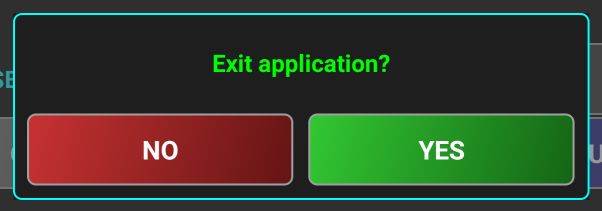
Press YES if you want to exit or on NO to return to the PocketRxTx startup screen.
Application graphical interface
![]() The application has 2 main screens: startup page and main
radio page. You can go from the startup page to the main radio page by pressing
orange START button. Go back to the startup page by pressing on the (Back)
icon.
The application has 2 main screens: startup page and main
radio page. You can go from the startup page to the main radio page by pressing
orange START button. Go back to the startup page by pressing on the (Back)
icon.
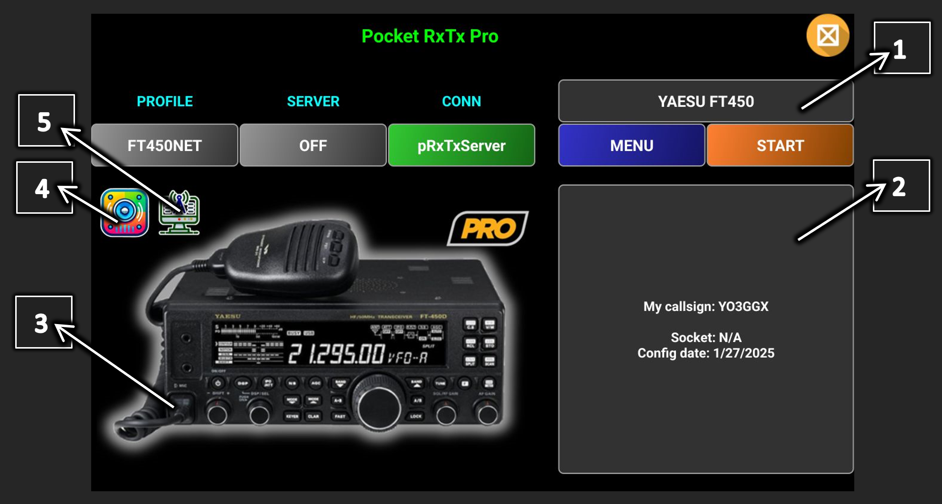
Startup page in WebSDR client mode
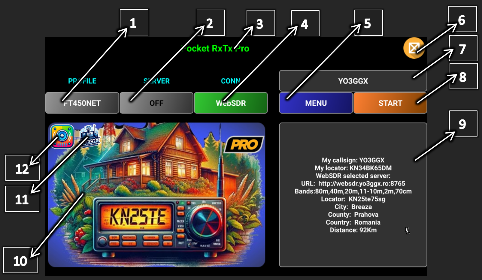
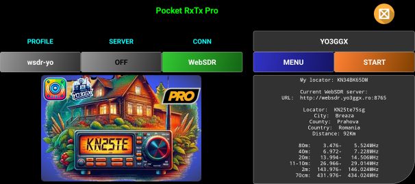
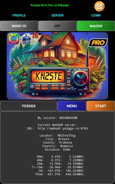
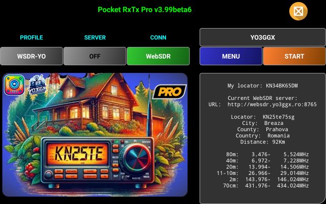
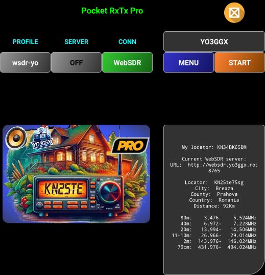
In the image below you can see a sample startup page in WebSDR client mode.

[1] – Button to select application profile, create a new profile or remove an existing profile. More details about using profiles here.
[2] – Button to activate/deactivate server mode and to configure server mode parameters. More details about the server mode here.
[3] – Application name and version (Lite, Pro or Beta).
[4] – Button to select connection mode (USB, Bluetooth, pRxTxServer or WebSDR). Click on each connection mode for more details.
[5] – Button to access application menu. More details about the menu here.
[6] – Click on this icon to exit the application.
[7] – Click on this label to get more details about the current WebSDR server or to select another one. When in MAP mode, the world map is displayed. When in LEGACY mode, a page with the WebSDR server data is displayed. For more details about the WebSDR client mode click here.
[8] – Press this button to go to the main radio page.
[9] – Here you will find more details about the currently selected WebSDR server and distance between your location and the server.
[10] – Here you will see an image of currently selected WebSDR server, as presented by the server owner. Pressing the image, a web site will be open with more information about the server and/or server owner.
[11] – This is logo of the selected WebSDR server.
[12] – This is an icon showing currently selected headset audio out device.
|
Icon |
Description |
|
|
Something wrong with the currently headset audio out device selection, please select a device. |
|
|
Generic Bluetooth Headset connected over A2DP (Rx only) |
|
|
Generic Bluetooth Headset connected over SCO (Rx and Tx) |
|
|
Generic USB Headset |
|
|
Phone/Tablet earpiece |
|
|
A wired headset connected to the smartphone/tablet |
|
|
Smartphone/Tablet in Speakerphone mode (You may be able to select different microphones if more than one available). |
|
|
BlueParrot B450-XT Bluetooth headset auto detected |
|
|
Inrico/Anysecu B01 Bluetooth Speaker/Mic auto detected |
|
|
Jabra Evolve Bluetooth headset |


In PRO version, when a Bluetooth headset or speaker/microphone is connected to the Android device, the battery level will be displayed in the top left corner of the audio device icon.
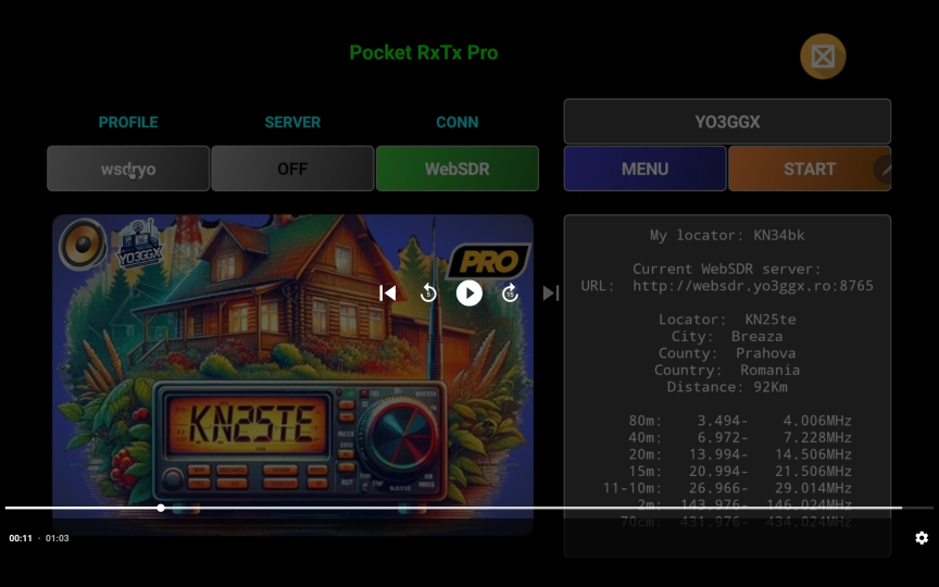
NOTE: A third icon may appear in the startup page.

When users tap on this “Easter Egg”, a short video is displayed. This video contains a special message that the developer wishes to share with users. Notably, the content of the video can be updated by the developer at any time, without requiring users to install a new version of the application.
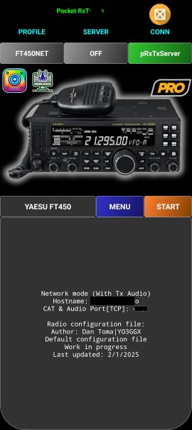
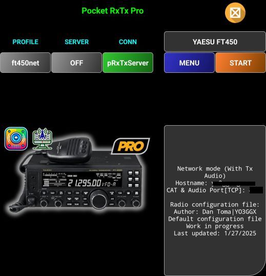
Startup page in Direct CAT mode
In the image below you can see a sample startup page in Direct CAT client mode. Only the differences are explained. For the rest of the controls see Startup page in WebSDR client mode here.

[1] – Press here to select another radio from local files (LOCAL) or from the central repository (ONLINE). If central repository is not available, or you are not connected to Internet, a local cache of the repository (embedded in the app) is used. Please note that this is based on the central repository at the date of the current application version release, so may not contain the latest versions for the radio configuration files. When ONLINE is selected, you are first prompted to select radio brand from a list and then the radio model for that brand. Currently selected brand and radio are marked with a green background button on the selection page.
In the specific case of an Yaesu FT8x7 radio, you are prompted with a warning message about the risk of directly accessing the radio EEPROM for the commands that are not available in the basic and very limited official protocol.
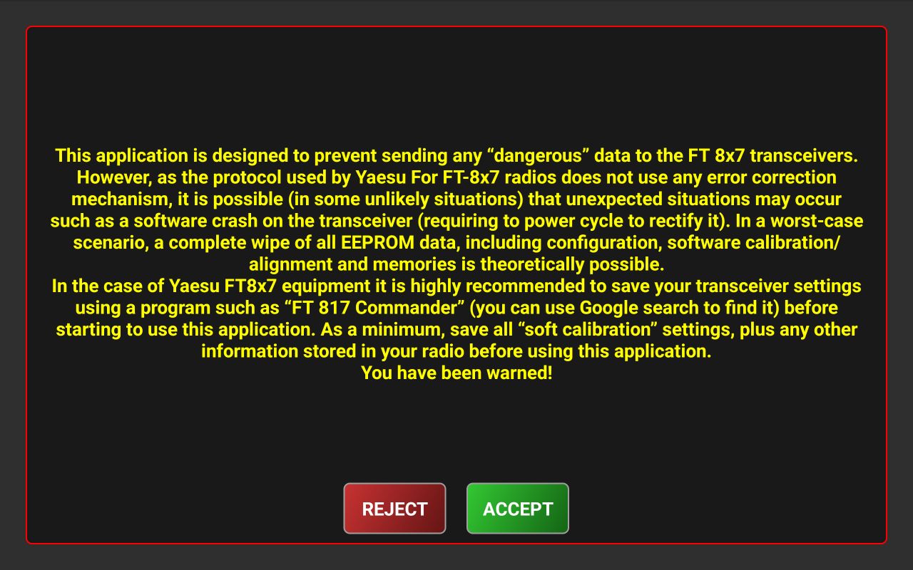
If you reject, all commands that writes directly in the EEPROM are disabled, but you can still read the associated parameters from the radio.
If you long press this button, you will be prompted to download the latest version of the radio configuration file from the central repository.
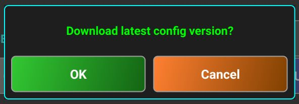
Press OK. After the file is downloaded, the info box is updated automatically. You can check the line “Last update”.
[2] – Here you will find details about the currently selected radio, connection mode and details and config file last update.
[3] – Here you will see a picture of the currently selected radio. If you tap the picture, the user manual of the radio is displayed (if associated link exists in the radio configuration file). If you long press on the radio picture, a document containing the CAT protocol is displayed (if associated link exists in the radio configuration file).
[4] – This is an icon showing currently select audio device. More details here.
[5] – This is an icon showing current connection mode. Can be one of the following:
|
|
Bluetooth connection |
|
|
USB connection |
|
|
Network connection to a pRxTxServer4 or another Pocket RxTx instance in Server mode |


Application GUI on different Android devices
The application screen is automatically adjusted based on the device screen size, screen ratio and orientation. In the following table you can see all available formats.
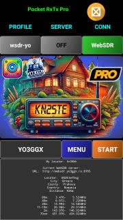
WebSDR mode startup screen formats
|
|
Portrait |
Landscape |
|
Modern Smartphones Display size: > 5” Screen rato: >= 16:9 |
|
|
|
Old Smartphones Display Size: < 5” Screen ratio: <= 16:9, >3:2 |
|
|
|
Tablets Display size: >= 7” Screen rato: <= 16:9, >= 4:3 |
|
|
|
Foldables(all) |
|
|
|
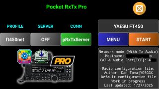
Network radios or old smartphones in compact mode Display size: < 5” |
|
|


WebSDR mode radio screen formats
|
|
Portrait |
Landscape |
|
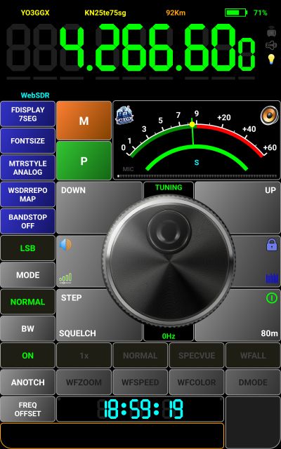
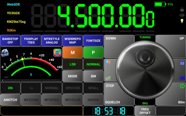
Modern Smartphones Display size: > 5” Screen rato: >= 16:9 |
|
|
|
Old Smartphones Display Size: < 5” Screen ratio: <= 16:9, >3:2 |
|
|
|
Tablets Display size: >= 7” Screen rato: <= 16:9, >= 4:3 |
|
|
|
Foldables(all) |
|
|
|
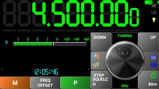
Network radios or old smartphones in compact mode Display size: < 5” |
|
|
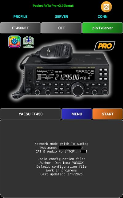
Direct CAT mode startup screen formats
|
|
Portrait |
Landscape |
|
Modern Smartphones Display size: > 5” Screen rato: >= 16:9 |
|
|
|
Old Smartphones Display Size: < 5” Screen ratio: <= 16:9, >3:2 |
|
|
|
Tablets Display size: >= 7” Screen rato: <= 16:9, >= 4:3 |
|
|
|
Foldables(all) |
|
|
|
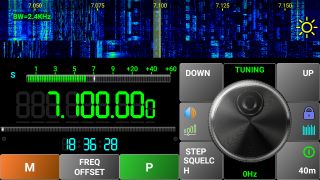
Network radios or old smartphones in compact mode Display size: < 5” |
|
|

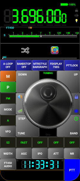
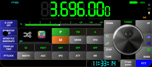
Direct CAT mode radio screen format
|
|
Portrait |
Landscape |
|
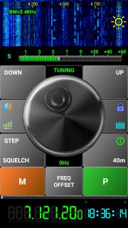
Modern Smartphones Display size: > 5” Screen rato: >= 16:9 |
|
|
|
Old Smartphones Display Size: < 5” Screen ratio: <= 16:9, >3:2 |
|
|
|
Tablets Display size: >= 7” Screen rato: <= 16:9, >= 4:3 |
|
|
|
Foldables(all) |
|
|
|
Network radios or old smartphones in compact mode Display size: < 5” |
|
|


NOTE: As the controls are the same (except for the small screen where some are missing), from now on, all images will be for a tablet in landscape mode.
Application profiles
You can define an unlimited number of application profiles (in the PRO version), or only two in the LITE version.
Selecting another profile
Tap the profile name in the startup page to display a selection panel with all the defined profiles.

Currently selected profile is marked in green. Tap on the profile you want to change to. All settings associated with that profile will be loaded in the application from the profile file.
Creating a new profile
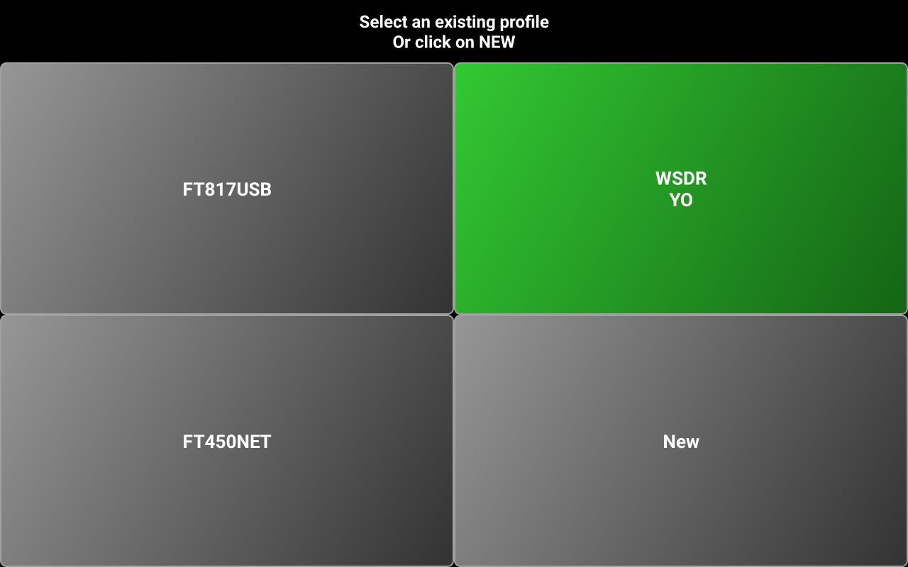
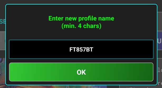
To create a new profile, tap on the New button in the profile selection page. You will be prompted to enter a name for the new profile.

After you enter the name, tap OK. Now you are asked to select connection mode.
NOTE: If you leave profile name empty and tap on OK, new profile creation is canceled.
Tap on the desired connection mode. You will be asked to select a radio.

If some radio configuration files were downloaded already for another profile, you will see the brand name followed by “(LOCAL)”. Follow the same process as when you created the first application profile. See here for the next steps.
Removing an existing profile
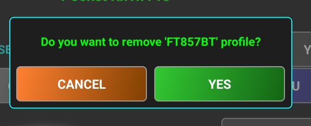
To remove an existing profile, you must first select it. Then long press the button with the profile name. You will be asked to confirm profile removal.

Tap YES to confirm. The profile will be removed from the device and first profile from the remaining list will be automatically selected. When only one profile is available on the device, you will show a notification that you are not allowed to delete it.
![]()
To be able to remove it, you must first create a new one.
Application Menu
Application menu has 4 main sections: CALLOG, RADIO or WEBSDR (depending on selected mode), SYSTEM and HELP.
As a rule, if a configuration has only 2 possible values (ON or OFF), respective button background will be set to Green of ON, or the default Gray when OFF.
The structure of the menu is presented on the following table.
|
LEVEL 1 |
LEVEL 2 |
- |
|
CALLLOG |
- |
|
|
MY QRZ (PRO only) |
- |
|
|
EMAIL (PRO only) |
- |
|
|
DELETE (PRO only) |
- |
|
|
WEBSDR |
- |
|
|
WSDRREPO (PRO only) |
- |
|
|
RADIO |
- |
|
|
|
- |
|
|
|
- |
|
|
|
EEPROM COMMANDS (only for Yaesu FT8x7 radios) |
- |
|
|
MIXED MODE (PRO only) |
- |
|
|
PTTKEY (PRO only) |
HW KEY DOWN/UP |
|
|
BLE KEY (learn) |
|
|
|
PTT TOGGLE |
|
|
|
PTT TOUCH |
|
|
|
RADIO OFF (PRO only) |
- |
|
|
RADIO ON (PRO only) |
- |
|
|
SCRIPTS (PRO only) |
- |
|
SYSTEM |
- |
|
|
- |
||
|
OFF |
||
|
ON |
||
|
SEND LOG BY EMAIL |
||
|
SHOW METERS RAW VALUE |
||
|
FDISPLAY (PRO only) |
- |
|
|
- |
||
|
- |
||
|
MEM STORE (PRO only) |
- |
|
|
MOUSE (PRO only) |
|
|
|
MTRSTYLE (PRO only) |
- |
|
|
MULTI USER (PRO only) |
- |
|
|
- |
||
|
UNIT (PRO only) |
- |
|
|
- |
||
|
HELP |
- |
|
|
- |
||
|
- |
||
|
- |
||
|
BUG REPORT (PRO only) |
- |
|
|
FEATURE REQUEST (PRO only) |
- |
|
|
- |
||
|
- |
CALLOG Submenu
Use this to edit your own callsign, configure QRZ connection credentials, send current call logs by e-mail, or delete it.
MY CALLSIGN
Tap this button to edit/modify your callsign. If you opt for multiuser mode (as described here), your callsign is stored per profile. If single user mode is selected, it is stored globally, for all profiles. You are prompted with a message box where current callsign is pre-filled.
After you modify it, press OK. If you don’t want to modify the current callsign, just press OK.
MYQRZ
NOTE: Available only in the PRO version.
After you press MYQRZ button, you will be prompted to enter your QRZ.com credentials. This will be required to do QRZ queries when logging calls.
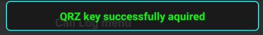
After entering username and password, tap OK button. If credentials are valid, a pop-up message will confirm this.
![]()
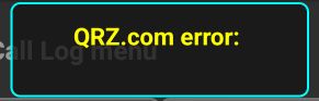
If the credentials are wrong, another pop-up will show up.
![]()
NOTE: Available only in the PRO version.
If you have data saved in the local call log, you can send the log through e-mail. If you do this for the first time, or if no default application defined for emails, you will be prompted to select it.

Usually, Gmail is installed on most Android devices. If you use another email application, select that one. Press Just once if you don’t want to set selected application as default, or Always and then you will not be asked again next time. An email will be automatically created, with the local call log as attachment.

The log file name (in ADIF format) will be used as email subject. Enter the destination email in the To field and then tap SEND button in the email application to send the email.
NOTE: If no call log is available locally, a pop-up message will notify you.
![]()
DELETE (Call Log)
NOTE: Available only in the PRO version.
By pressing the DELETE button you delete locally stored call log. You will be prompted to accept this.

Press YES if you want to delete, or NO otherwise. If YES pressed, a pop-up will confirm the operation.
![]()
NOTE: If no call log is available locally, a pop-up message will notify you.
![]()
WEBSDR Submenu
This submenu is available only in WebSDR mode or in Direct CAT mode when Mixed Mode is activated. Use this to access WebSDR FAQ web page, select the communication protocol with the WebSDR server and the way the WebSDR servers are presented.
BAND STOP
This allows you to select band limits based on one of the 3 IARU regions. If one of regions is selected, you will not be able to tune (using the knob or UP/DOWN buttons) outside of the allocated frequency range for the currently selected band.

This prevents the possibility of transmitting outside legal HAM bands by mistake.
WSDRREPO
Tap this button to select the way the available WebSDR servers are presented: as a selection panel with a button for each server (LEGACY) or on a world map, with pinch/zoom functionalities (MAP). Second one is only available in the PRO version of the application. More about using WebSDR mode here.
RADIO Submenu
Use this submenu to set different features for the Direct CAT operation. For most of the radios, the submenu will have 8 buttons.
BAND STOP
This allows you to select band limits based on one of the 3 IARU regions. If one of regions is selected, you will not be able to tune (using the knob or UP/DOWN buttons) outside of the allocated frequency range for the currently selected band.
EDIT CONFIG FILE
NOTE: Available only in the PRO version.
Use this to edit the radio configuration file locally, on your Android device, in a very simple text editor.
Tap here to learn more about the radio configuration file syntax.
EEPROM COMMANDS (only for Yaesu FT8x7 radios)
This setting is available only when current radio is one of the following: Yaesu FT817, FT818, FT857 or FT897. For these specific radios, many of the usual parameters can be set only by using direct write to the radio EEPROM.
WARNING: It can be very dangerous to modify EEPROM locations. If you have not saved all the transceiver configuration before using this application is better not to use it with an FT8x7 transceiver. Although I took a reasonable number of precautions in the code, use this feature at your own risk!
When it is set to OFF, all CAT commands that require EEPROM write are blocked, no matter what you write in the radio configuration file. Read commands that read parameters value directly from the EEPROM will not be blocked, so you can still get that information from the radio.
MIXED MODE
NOTE: Available only in the PRO version.
When this mode is activated, you will be able to receive using both the radio and a pre-selected WebSDR server and to transmit using your own radio. More about the Mixed Mode here.
PTTKEY
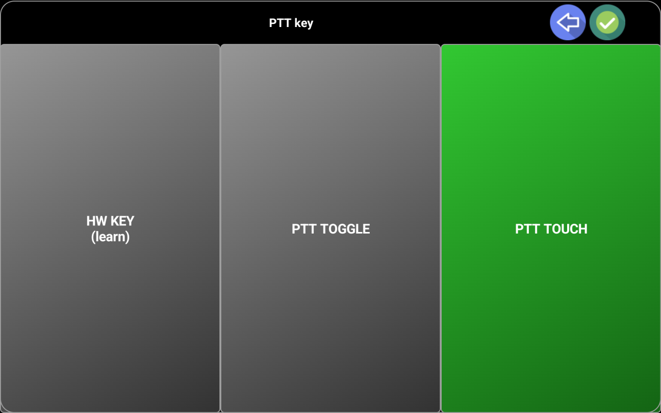
Use this to set how PTT button works. When you tap on PTTKEY for the first time, the following selection panel will be displayed.
HW KEY DOWN/UP (learn) is used to define a device hardware key to be used as PTT button. Some smartphones may have a camera shutter button. The very popular network radios based on Android have a dedicated PTT button. This can be used as PTT in the application.
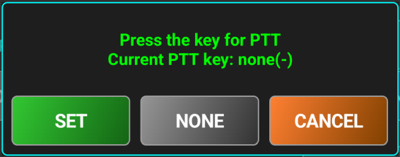
After you tap on HW KEY DOWN/UP (learn), you will be prompted to press the hardware key code to be used for PTT down. Let’s say we can use Volume Up as PTT key. Press it and keep it pressed.

Tap SET to save the keycode for PTT down.
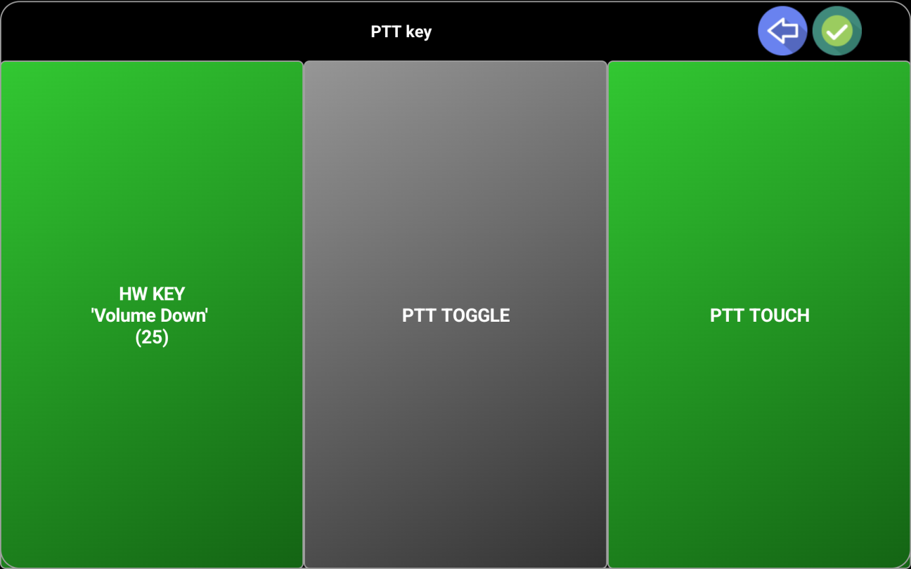
Release the PTT button (Volume Up in this case) when asked. Tap SET to set the keycode for PTT up. In this case, the same key code is used for both PTT Up and PTT Down, with two different actions (PRESS/RELEASE). Some devices may have different codes for press and release.

If you want to remove the key assignment, just tap NONE. The assignment will disappear in the PTT key panel.
RADIO OFF
NOTE: Available only in the PRO version.
This setting is available only if in the radio configuration file there is a definition for radio power on/off (SET_POWER=…). If this is missing, the option will not appear at all. If active, the radio will be automatically powered on when the connection is established.
RADIO ON
NOTE: Available only in the PRO version.
Like for RADIO OFF, this setting is only available if in the radio configuration file there is a definition for radio power on/off (SET_POWER=…). If this is missing, the option will not appear at all. If active, the radio will be automatically powered off when disconnecting from the radio.
SYSTEM Submenu
ALWAYSON
When activated, the device will remain on for the entire time the application is displayed in the foreground.
An icon will be shown in the radio panel (right of the frequency display) showing that.
|
|
ON |
|
|
OFF |
COMPACT
This setting is available only for Android devices with the screen size below 5”. Can be very useful especially for the Android based Network Radios with small screens (3-5”).
When activated, radio panel will contain smaller number of controls, for better usability, but most of the main application functionalities will not be affected. Tap here to see how the screen looks in compact mode.
DEBUG
This submenu can be used to set some useful debugging features.
OFF – Disable debug logging
ON – Enable debug logging
NOTE: Debug log is never cleared but truncated to the last 1000 lines when you close the application or move it to the background.
SEND LOG BY EMAIL – If a log was previously created, you can send it by email. A new email is automatically created, pre-filled with all the details including recipient (support address) and with the log file attached.

If you think it can be useful, you can add more comments in the email before sending it.
SHOW METERS RAW VALUE – this feature can be very useful to calibrate the meters for your specific radio, if the calibration data from the default radio configuration file does not provide enough accuracy for your radio. If you activate it, when connected to the radio, in the status bar you will show row and decoded value for the selected meter.
![]()
RAW value represents the numeric value returned by the radio. In the case of the SMETER, S0 correspond to 100, S1 to 200, …, S9 to 900, then S9+10 to 910, S9+20 to 920, …, S9+60 to 960. The application will try to interpolate the values between the calibration poinys, saved in the CALIB_xMETER, where x can be S, SWR, PWR, ALC, MOD or VLT.
Then in the calibration line from the radio configuration file, you can add the calibration point resulting from the info above.
CAL_SMETER=0=0,,82=450,…
HINT: If for an unknown reason the application hangs, or you get a blank screen, try first to rotate the screen. If the problem persists, you can press VOLUME-UP and VOLUME-DOWN at the same time on your device and the application will be forcibly closed.
More details in the chapter dedicated to the radio configuration file here.
FILES IMPORT EXPORT
This is used to transfer the files from Pocket RxTx to pRxTxServer4 (for backup purposes) and back (for restore purposes). To use this feature (available only in the PRO version of the app), you must run pRxTxServer4 (java app) on a PC/Mac and set a functional network connection first, as described here. You will be prompted to choose between IMPORT and EXPORT. When in USB/Bluetooth mode, FILE EXPORT just copies the files to the device internal storage (Internal Storage/Android/data/ro.yo3ggx.prxtx…/files), to make them accessible when connecting the device to a PC.
If you tap EXPORT, app configuration file(rxtx.cfg), all profile (*.prf4), radio configuration files(*.radio4), ADIF files (*.adi) and voice messages (*.wav) are automatically sent to the PC/Mac where pRxTxSever4 runs, in a subfolder named prxtxbck. At the end, network connection is closed automatically.
If you tap IMPORT, a list of available files (of the type mentioned above) is returned from the server.
Tap on the file you want to import back to PocketRxTx.
If a file with the name 'history.adi' is imported, it will be used for lookups in the call log (when this feature will be available). The app will never write in this file.
NOTE: If a file with the same name is already available locally, it will be overwritten without notification.
If you import a profile file and respective profile does not exist in the local profiles list, it will be automatically added.
FDISPLAY
NOTE: Available only in the PRO version.
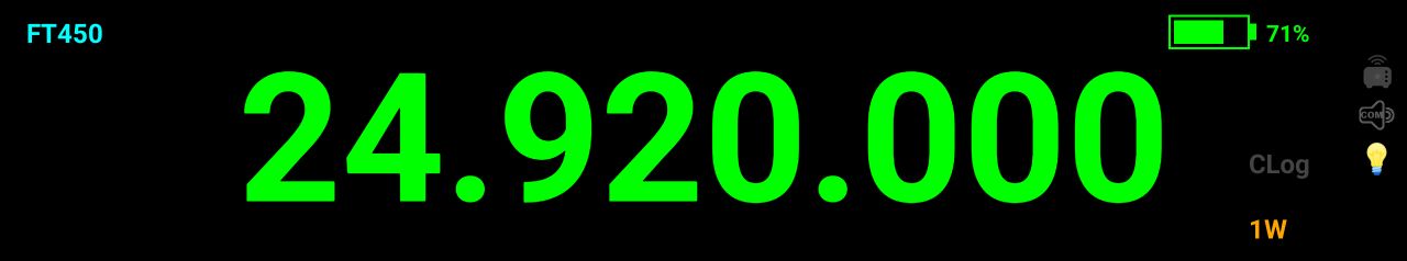
You can set the look of the frequency display: LEGACY (standard rounded digits)
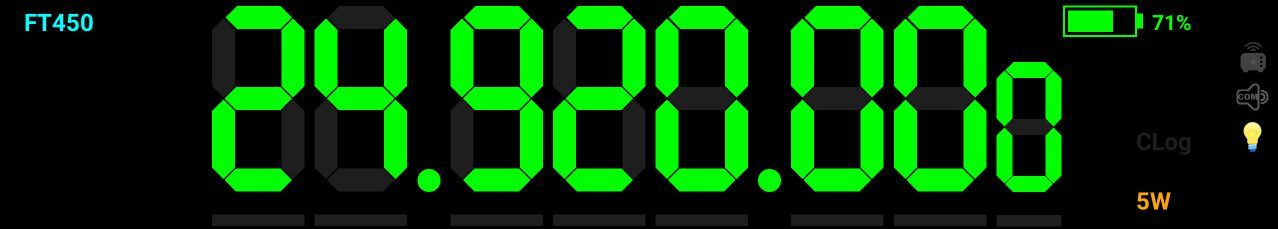
or 7SEG (7-segments type digits).

7 segments mode provide one more feature: you can tap on a digit to select it. A green bar will be displayed under the digit to show you that the selection was acknowledged.
Then you can use UP/DOWN buttons or the tuning knob to adjust the frequency for the selected digit. In the example above, step is 1KHz. To unselect a specific digit and return to the standard tuning mode based on preset step, tap again that digit, or outside the digits area.
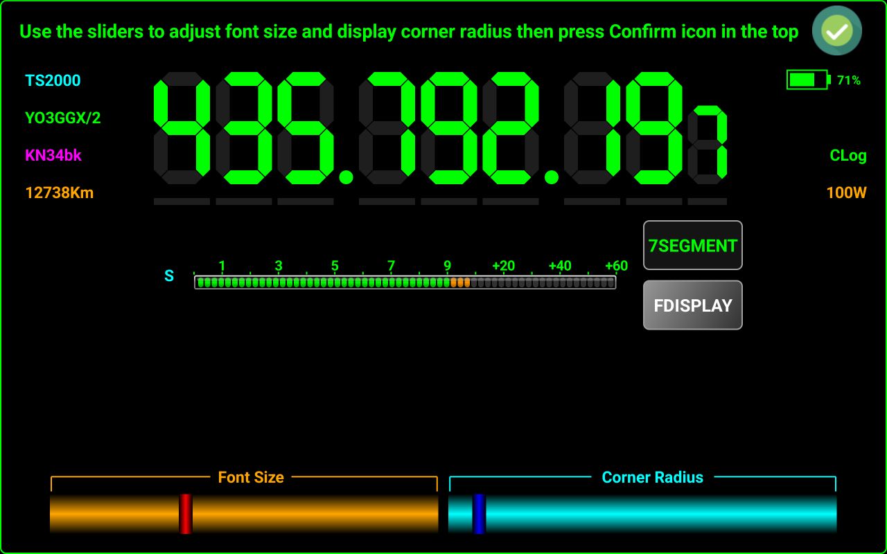
FONT SIZE
You can adjust application font size and display corner radius at any time.
It is recommended to adjust the font size (using the red slider) just before the point where the text “7SEGMENT” starts to wrap on the second line. Adjust corner radius with the blue slider (for devices with rounded corners displays) at the limit before the green frame around the screen starts to be cropped in the corners. Tap on the Confirm green icon in the top right of the screen when ready.
MEM STORE
NOTE: Available only in the PRO version.
You can select between PROFILE (memories stored in the profile) and GLOBAL (memories stored in the application configuration file). In the LITE version, memories are always stored globally, so you can have a maximum of 16 memory locations. In PRO mode, you can have up 99 memories per profile, so the number of memory locations is unlimited, as the number of profiles is not limited in the PRO version.
MOUSE
NOTE: Available only in the PRO version.
This setting can have 2 values:
SYSTEM - use the mouse as usual, you can click or long click on the buttons or other views from the panel (similar with the touch tap). Can be useful on Chromebooks without a touch screen, or when running the application in an emulator without touch support.
APP – Use mouse wheel for tuning, with the same step as for the frequency tuning knob from the graphical interface. Left button works as PTT and right button as MUTE toggle. Mouse wheel will work as a tuning knob no matter where the mouse pointer is situated. Most of the time, the cursor will be hidden.
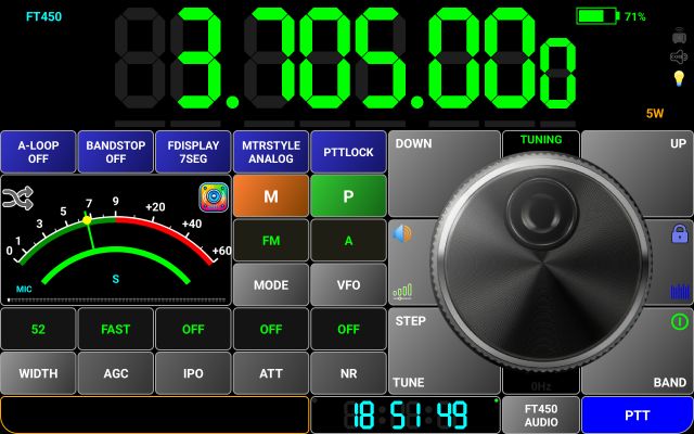
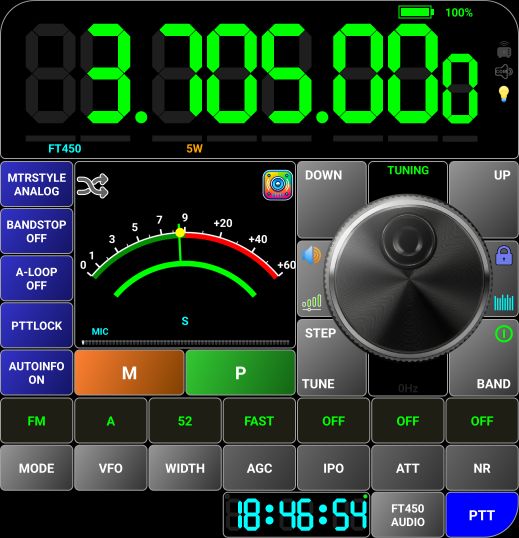
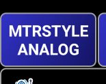
MTRSTYLE
NOTE: Available only in the PRO version.
You can select between ANALOG
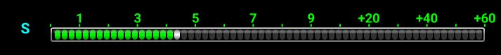
or BARGRAPH
![]()
The meter scale is automatically adjusted depending on the selected meter and for the PWRMETER depending on the maximum TX power for the selected transceiver either, for maximum resolution.
In the Lite version, only BARGRAPH meter is available.
MULTIUSER
NOTE: Available only in the PRO version.
If MULTIUSER mode is activated, user specific data (callsign, own locator and QRZ credentials) are stored in the profile, so each time you create a new profile this information will be requested again. If OFF, this data is stored globally, so you cannot have more than one user operating the application.
RESET
This is used to reset the application to factory default, clearing all data. You will be prompted if you want to do it.
If you tap NO, you will return to the startup screen. If you tap YES, profiles and configuration data will be fully erased and application closed. When you start the application again, you will be in the same situation as after a fresh installation, at first start.
UNIT
NOTE: Available only in the PRO version.
You can select between METRIC or IMPERIAL for the unit. This is used for example when showing distance between your location and selected WebSDR server on the map or in the information box.
VIBRATE
You can activate/deactivate haptic feedback when you tap on the screen. Usually, this feature works only on smartphones.
HELP Submenu
This submenu has 4 sections.
ABOUT
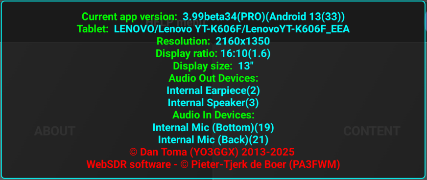
When you tap on ABOUT, details about the hardware and software are displayed in a box, as in the example below.
Usually, all this information is automatically sent in the email created when sending the log file. More details here.
Tap on the details window to close it.
CONTENT
This is used to access the online application user guide (multilingual). You can select the language from the dropdown box at the top of the page.
APPLICATION HISTORY
Here you get a changelog containing all the bug fixes and changes from the last major release (4.0 in this case). This is a table that is updated in real time. Both bug fixes and changes are presented here. At the end you can find another table containing a Wishlist, with features to be implemented in future versions.
APPLICATION FORUM
Here you can access Pocket RxTx v4 application section from the YO3GGX forum. This is the only way to get support for the LITE version.
BUG REPORT (PRO only)
E-mail support is available only in the PRO version. Tap this button to automatically create a new e-mail containing some technical details about your setup that can help in troubleshooting potential issues you may have with the application. Add more details about your issue or your feedback/feature request.
FEATURE REQUEST (PRO only)
Tap on this button to request a feature to be added to the Wishlist. After I accept it, this will appear on the table at the end of the page here.
VIDEO GUIDE
Tap here to play a YouTube video containing a guide about how to use different application features.
NOTE: This video guide is a work in progress and will be updated continuously. Currently only part of the features are described. The audio language for the video guide is English. In the PRO version, you have the option to activate subtitles. The following languages are currently supported for subtitles: English, Romanian, French, German, Spanish, Italian and Portuguese. At the moment of this user guide release (rev 5), subtitles are available just as a preview, for the Introduction chapter only. As time will permit, more subtitles will be added.
When you tap on VIDEO GUIDE, the following panel will be displayed.

You can scroll through the chapters list by dragging the list vertically. When in landscape mode, the list of chapters is automatically removed from the screen if nothing touched for ~6s. To re-open the chapters list at any time, tap on the upper half of the screen. In this way the video is always played in full screen mode.
When in Portrait mode, the list is always visible.
You can rotate the screen to look at the video in full screen mode. In the PRO version, tap on the green OFF button in the top left corner to select the language for the subtitles and the chapters title.

Let’s say we select Spanish. The chapters title will change
to Spanish. When subtitles are available for a specific chapter, the symbol ![]() is
shown in front of the chapter tile. To play the video for a specific chapter, just
tap on the chapter title. The list will be hidden and playback will
automatically start.
is
shown in front of the chapter tile. To play the video for a specific chapter, just
tap on the chapter title. The list will be hidden and playback will
automatically start.
You can tap in the bottom half of the screen to display video player controls.
When paused, the controls remain on the screen. When in play mode, controls are automatically removed in a few seconds. You can toggle controls on/off by tapping the bottom half of the screen.
To close video guide, tap on the ![]() icon
in the top right corner of the chapters list or on Exit (last item from the chapters
list).
icon
in the top right corner of the chapters list or on Exit (last item from the chapters
list).
YO3GGX PROJECTS
Here you can read more about my other hardware and software projects.
Operating the application in WebSDR mode.
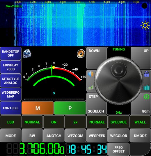
WebSDR panel
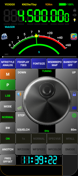
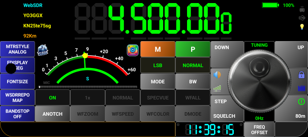
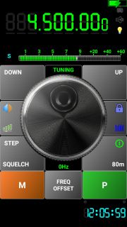
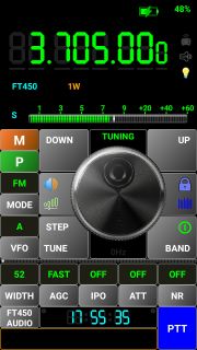
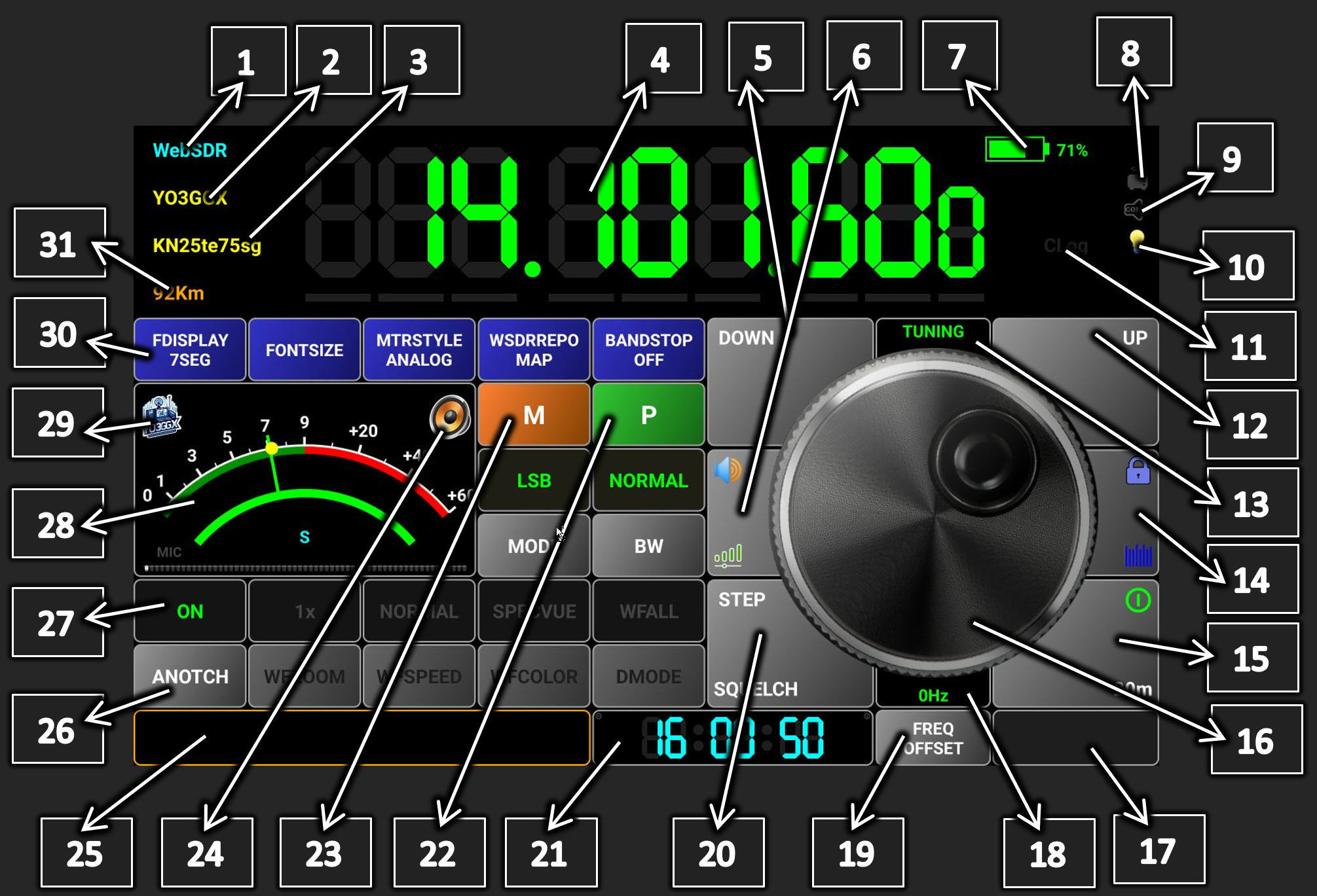
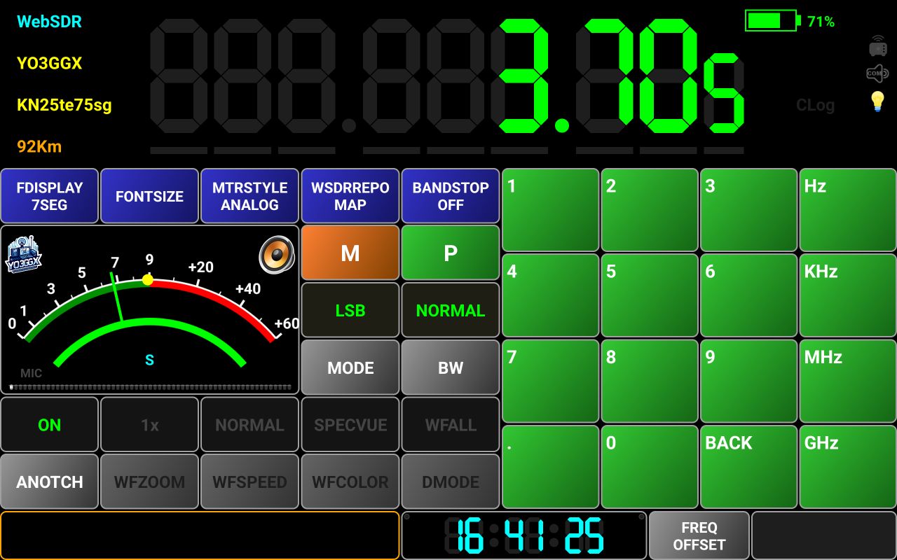
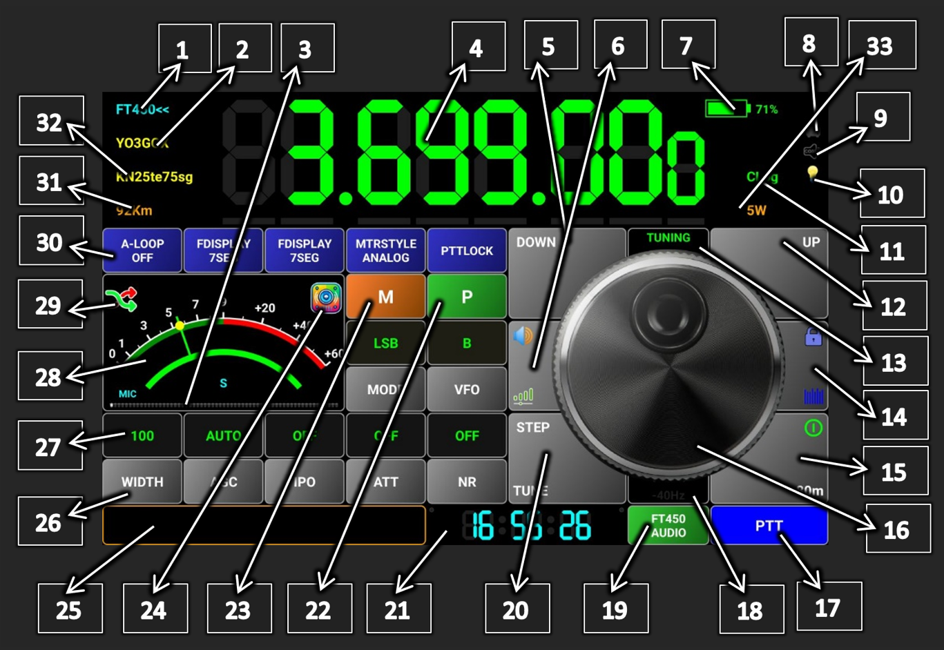
This is how the radio page looks in the WebSDR mode.
[1] – Current mode (WebSDR).
[2] – Selected WebSDR server callsign.
[3] – Selected WebSDR server locator (6-10 chars)
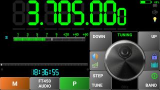
[4] – Frequency display. Dots are presented between 100Hz and 1KHz, between 100KHz and 1MHz and between 100MHz and 1GHz. You can change the frequency in several ways, as described here.
· Using the tuning knob. Frequency step in this case is the fine step defined in the radio configuration file (for AUTO) or user selected step (see [20]).
· Using Up/Down buttons. In this case, brute step from the radio configuration file is used (for AUTO) or 10x the fine step selected by the user (see [20]).
· When in 7 segments mode (PRO only), check here for more tuning options.
· By selecting a specific digit (only for PRO version when 7 segments display mode selected). Tap on a digit you want to increment or decrement. A green bar will be displayed below the digit, to show you that it was selected.
You can now change the frequency with that step using the tuning knob or Up/Down buttons. When ready, tap outside the digits area to clear the selection. The green bar will disappear.
· By direct frequency enter. Long press the frequency display. Tuning knob area will be replaced by a numeric keypad.

Tap the frequency you want (in Hz, KHz, MHz or GHz) and then the respective button. In the example above, 3.705 was typed, then MHz button to enter 3.705MHz. You can clear last digit by tapping BACK button. You can return to the normal radio screen without changing the frequency by long pressing on BACK button, if you don’t want to enter the frequency.
[5] – Frequency Down button, used to change the frequency with a negative brute step (usually 10 x tuning knob step).
[6] – When tapping this button, you can adjust the audio level. This is independent from the phone volume physical buttons. The meter scale will change to 0-100%, meter name to VOL and the button background color to green.
The black label in the top of the tuning knob will show current mode as VOLUME. Use the tuning knob to adjust the audio volume. When ready, tap the button again to return to normal operation.
[7] – Here the current battery level is displayed, in the PRO version only. In the LITE version, this symbol is grayed out.
[8], [9] – These icons are not used in WebSDR mode.
[10] – This icon will be on when Always ON mode is activated. See here for more details about what this mode means and how to activate it.
[11] – Clog symbol is on when call logging is activated. See here for more details about Call Logging.
[12] – Frequency Up button, used to change the frequency with a positive brute step (usually 10 x tuning knob step).
[13] – Here you can see the current function for the tuning knob (TUNING, VOLUME or F-OFFSET).
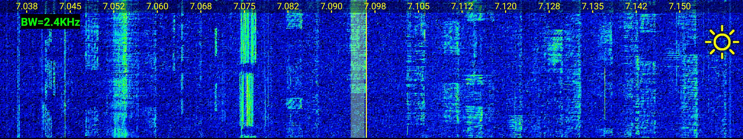
[14] – This button has 2 functions. When two icons or words are on a button, lower one means the function for tap and the upper one the function for long press. In this case, if you tap this button, you activate/deactivate the waterfall. If you long press it, you toggle screen lock. When you activate the waterfall, the whole frequency display is replaced by the waterfall.
On top
of the waterfall is the frequency scale. In the top left you can see current
bandwidth. In the right, there is the symbol ![]() .
Drag this symbol vertically to adjust waterfall brightness according to your
preferences. Drag it in the upper direction to increase the brightness or drag
it down to decrease it.
.
Drag this symbol vertically to adjust waterfall brightness according to your
preferences. Drag it in the upper direction to increase the brightness or drag
it down to decrease it.
[15] – Long press this button to connect to the WebSDR server (ON/OFF button). When it is already connected, long press this button to disconnect from the WebSDR server. If you tab this button when connected to the server, you can select the band from the ones available on the current WebSDR server.
Currently selected band is marked in Green.
[16] – This is the tuning knob but can be used for volume adjustment or to set frequency offset too.
[17] – This area is not used in WebSDR mode.
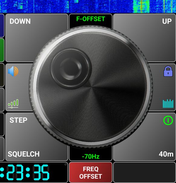
[18], [19] – Here you can see current frequency offset (defaults to 0) between displayed and real frequency. Some WebSDR servers are not well calibrated. You can compensate for this in the application by setting the frequency offset.
Press on FREQ OFFSET button [19] and then use the tuning knob to adjust it. [13] will change to F-OFFSET and FREQ OFFSET button will change to red.
Tune to a known frequency and then rotate the knob until you hear the expected signal. Then press FREQ OFFSET button again to save the value for the current WebSDR server and band. Next time when you select the same server and band, the frequency offset will be automatically applied.
[20] – Tap on this button to toggle Auto Squelch functionality from the WebSDR server. When active, the button background is green.
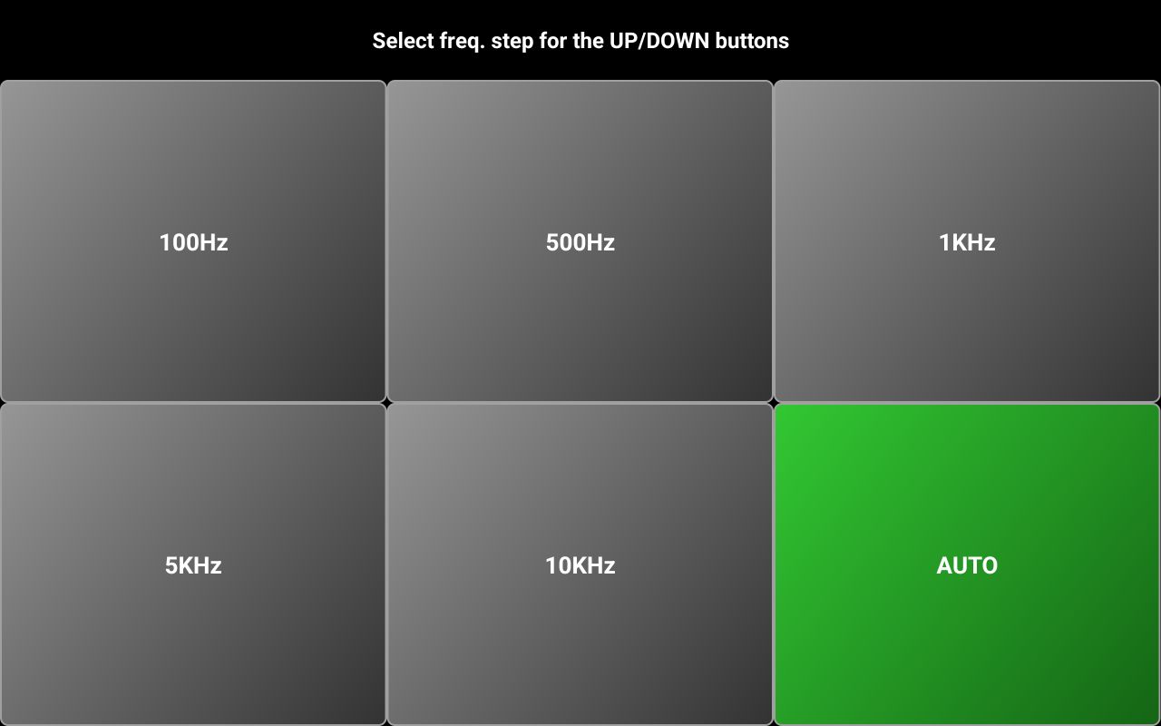
Long press on this button to set the frequency step for the tuning knob. A selection panel will be displayed.

When AUTO mode is selected, the frequency step defined in the radio configuration file is used. For more details about the radio configuration file, tap here.
[21] – An UTC clock is permanently visible in this area. If you tap on the UTC clock when connected to the WebSDR server, call logging is activated. Tap here for more details about call logging.
[22] – This button shows “SET” when disconnected from the server and “P” when connected for the server. Tap on this button when disconnected from the WebSDR server to select the WebSDR server and/or audio device. This is useful only in COMPACT mode, when the dedicated icons are not available.
As the function is similar, check [29] and [24] for more details about WebSDR server and audio device selection.
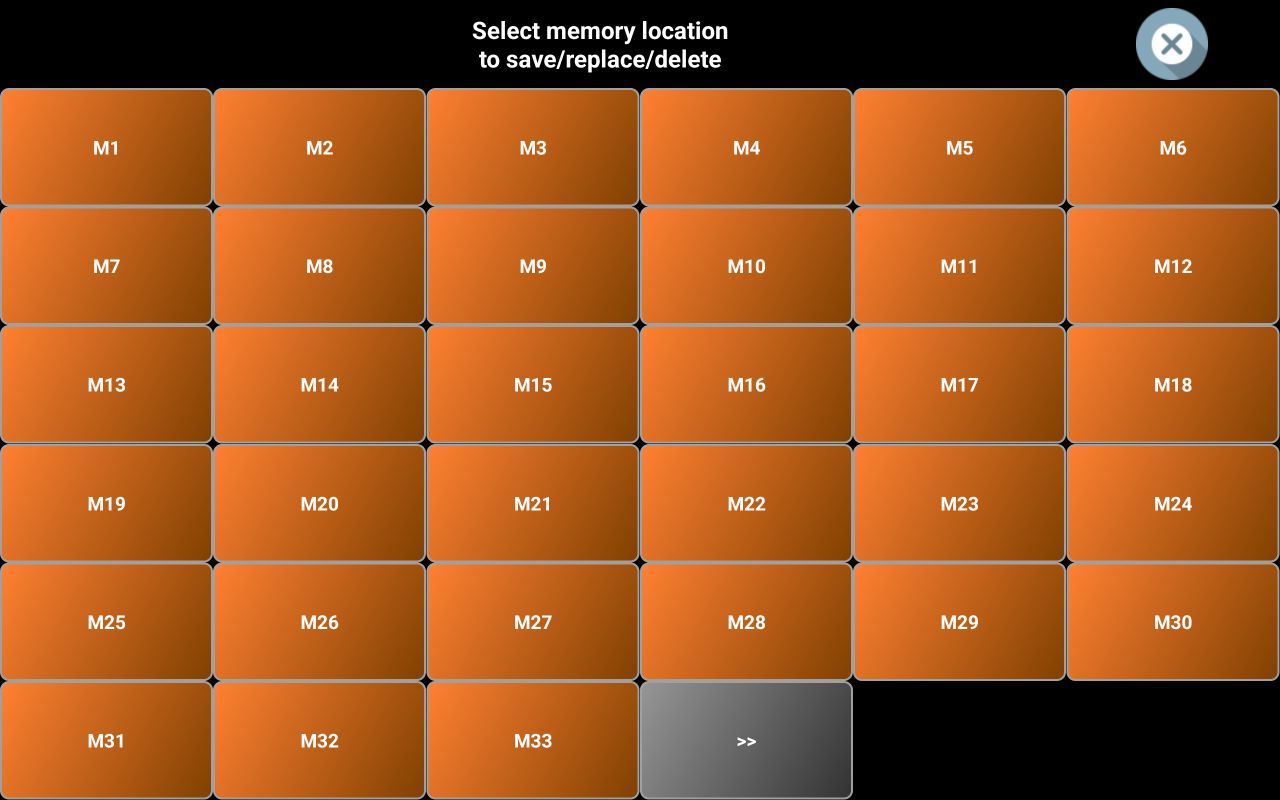
[23] MEMORY button is used to recall a memory location or to save current settings to a new memory location. To save current settings to a new memory location, long press on the M button. You will be prompted to select one of the 99 available memory locations.
NOTE: In the LITE version, only 16 memory locations are available.
To go to the next page of 33 locations, tap on >>. To go to the previous page with 33 locations press <<.
Tap on the memory location you want to use.
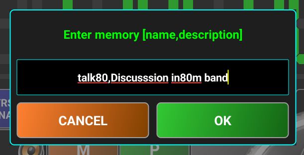
You will be prompted to enter a name for the memory location (7-8 chars maximum) and a description, separated by a comma. Tap on OK when ready. A pop-up will confirm that the memory location was saved. All defined memories are now part of the profile file, no more use dedicated files. In the LITE versions, all up to 16 memories are saved in the global app configuration file.
To recall a memory location, tap on M and then select memory location you want to recall.
In WebSDR mode, we can have 2 types of memories: local and server based. Server based memories are defined by the server owner and marked in the application with a green background. Locally defined memories are marked with an orange background. Tap on the location you want to recall. All saved parameters will be loaded and the WebSDR server set accordingly. Server based memories cannot be edited or removed.
NOTE: Not all WebSDR servers have server-based memories defined.
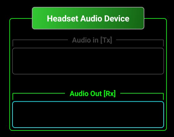
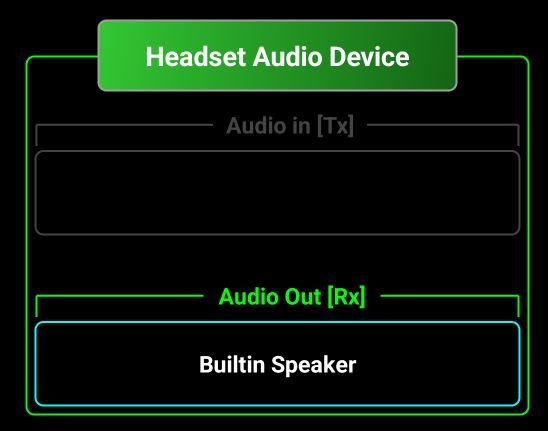
[24] – Tap on this icon to select the audio device. In WebSDR mode only Audio Output device can be configured. To select another audio device, tap on the audio icon.
Tap the field with a cyan border and select one of the available devices, let’s say Builtin Earpiece.
[25] – This is the status info area. Here different messages will be displayed and when Waterfall is visible (covering the main frequency display), tuned frequency will be displayed here.
![]()
The standard functionality of the frequency display area will be available here too (digit selection, direct frequency entry through long press).
[26] – In WebSDR mode, all 8 parameter buttons are predefined, and assignment cannot be changed. We have the following parameters in WebSDR mode:
MODE – reception mode, you can select between LSB, USB, CW, AM, FM.
BW – Rx bandwidth. You can select between NORMAL, NARROW1, NARROW2, WIDE1 and WIDE2. IN the table below you can see the effective bandwidth depending on the selection and reception mode.
|
Rx mode |
Selection |
Bandwith frequency limits |
|
LSB |
NORMAL |
-2.7KHz, -0.2KHz |
|
NARROW1 |
-1.5KHz, -0.2KHz |
|
|
NARROW2 |
-2KHz, -0.2KHz |
|
|
WIDE1 |
-3.5KHz, -0.2KHz |
|
|
WIDE2 |
-4KHz, -0.2KHz |
|
|
USB |
NORMAL |
0.2KHz, 2.7KHz |
|
NARROW1 |
0.2KHz, 1.5KHz |
|
|
NARROW2 |
0.2KHz, 2KHz |
|
|
WIDE1 |
0.2KHz, 3KHz |
|
|
WIDE2 |
0.2KHz, 4KHz |
|
|
CW |
NORMAL |
-0.9KHz, -0.6KHz |
|
NARROW1 |
-0.77KHz, -0.73KHz |
|
|
NARROW2 |
-0.78KHz, -0.72KHz |
|
|
WIDE1 |
-0.95KHz, -0.55KHz |
|
|
WIDE2 |
-1KHz, -0.5KHz |
|
|
AM |
NORMAL |
-3KHz, 3KHz |
|
NARROW1 |
-2KHz, 2KHz |
|
|
NARROW2 |
-2.5KHz, 2.5KHz |
|
|
WIDE1 |
-3.5KHz,3.5KHz |
|
|
WIDE2 |
-4.5KHz, 4.5KHz |
|
|
FM |
NORMAL |
-8KHz, 8KHz |
|
NARROW1 |
-3KHz, 3KHz |
|
|
NARROW2 |
-5KHz, 5KHz |
|
|
WIDE1 |
-25KHz, 25KHz |
|
|
WIDE2 |
-50KHz, 50KHz |
ANOTCH - Tap here to toggle AUTONOTCH. This is very useful when a carrier overlaps the base signal. Will be automatically removed without affecting the base signal.
SQUELCH – this is an auto squelch; you don’t have to adjust it. When active, the button background goes Green.
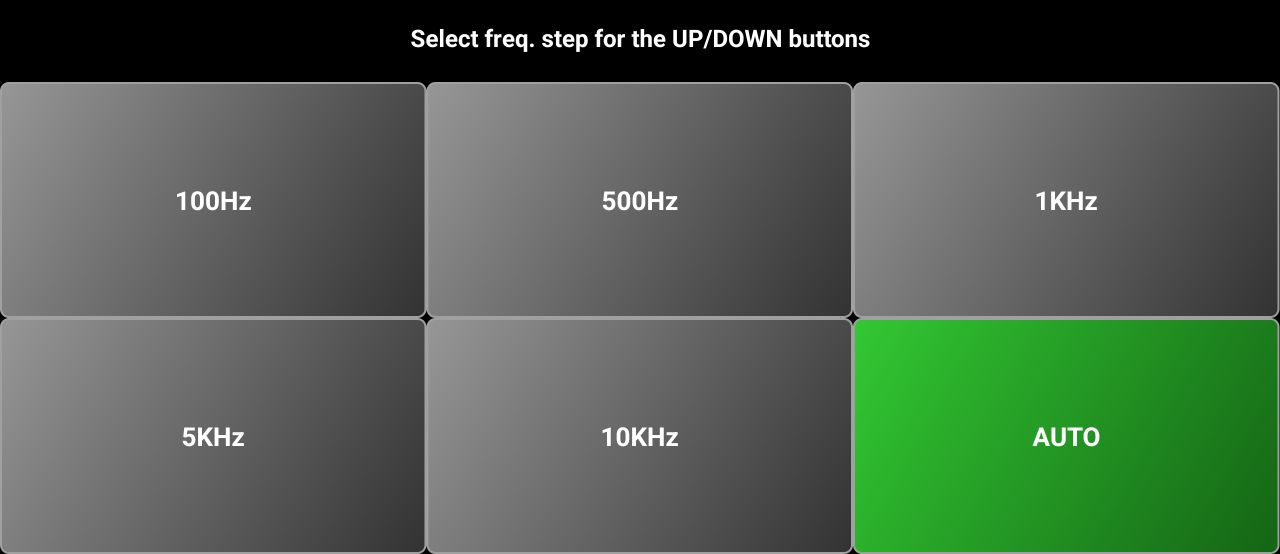
STEP – Long press on the SQUELCH button to set the frequency step for the Up/Down buttons. The step for the tuning knob will be 10 times smaller.

In AUTO mode, the step is set based on the frequency, as follows.
|
Frequency range [MHz] |
Fine Step (Tuning Knob) [KHz] |
Brute Step (Up/Down) [KHz] |
|
0.1 – 26.899999 |
0.01 |
1 |
|
26.89 – 27.404999 |
0.01 |
10 |
|
27405 – 29.999999 |
0.01 |
1 |
|
30 – 137.999999 |
0.01 |
5 |
|
138 – 173.999999 |
0.01 |
6.25 |
|
174 – 445.999999 |
0.01 |
25 |
|
446 – 446.199999 |
0.01 |
12.5 |
|
446.2 - 1300 |
0.01 |
25 |
The next 4 buttons are active only when the waterfall is visible.
WFZOOM – you can set the waterfall zoom from x1 up to x64, depending on the coverage for the currently selected band. If the band covers only 48KHz, you can have a maximum zoom of x2. If the coverage is 2.048MHz (maximum possible for a WebSDR standard server), maximum zoom is x64. If you long press on this button when the zoom is > x1, it will be reset to x1.
WFSPEED – set the waterfall speed. Possible values are: NORMAL, SLOW or FAST.
WFCOLOR – select the waterfall pallete. This is available only in the PRO version. Possible values are B&W (Black and White), SPECVUE (SpectraVue), SDRSHP (SDR Sharp) or RGB. In the LITE version is always B&W. SPECVUE is the default pallete for the PRO version
DMODE – Display Mode. You can select between WFALL (Waterfall) and SPECT (Spectrum). This is how it looks in Spectrum mode.

[27] – Here you can see the current value for the parameter from the button below.
[28] – The meter can be a bargraph or an analog style one. In the LITE version only the bargraph type is available. In WebSDR mode, the meter will be always the SMETER.
[29] – The WebSDR server logo for the currently selected server will be displayed here. If you tap on it, you will be able to select another server. More about WebSDR server selection here.
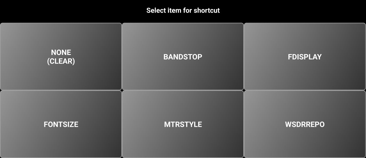
[30] – You have 5 blue user programable buttons. When you run the application for the first time, all 5 are empty (nothing assigned to them). To assign a function to them, long press on a blue button. You will be prompted to select what function to assign. These are the options in WebSDR mode.

If you tap on a specific function, the text of the button will change to the function name and current value.
![]()
Tap NONE (CLEAR) if you want to remove a previous assignment.
[31] – The distance between your current location and the WebSDR server is displayed here in orange color. Depending on the UNIT selection from the menu (see here), the distance is in km or in miles.
Selecting WebSDR server
You can select the WebSDR server in two ways.
· From the startup page, by tapping on the current server callsign in the startup page (YO3GGX in the image below).
![]()
· From the radio panel, by tapping the server logo, present in the meter area.
![]()
Depending on the WSDRREPO selection (MAP or LEGACY, see here), the list of available WebSDR servers will be presented in a different way. In LITE version, only LEGACY is available.
WebSDR server’s repository (LEGACY mode)
The list of servers is presented as a selection panel.

When
first accessed, only active servers are displayed. For each server you can see
the associated callsign, city and country. Currently selected server is marked
in green. If you tap the Refresh icon ![]() , all the servers that are registered with the
application will be checked again. You can see the progress.
, all the servers that are registered with the
application will be checked again. You can see the progress.
![]()
This time, the servers that are currently offline will be displayed too, in red.
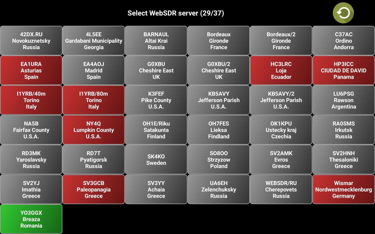
Tap on the server you want to select.
WebSDR server’s repository (MAP mode)
When you enter the repository, the map will be displayed zoomed in, to show your current selected server and your location.
For the
currently selected WebSDR server, the list of available bands and frequency
ranges are displayed in a green box. A red line is drawn between your and
server location, with the distance on it. You can use pinch gestures (or +/-
buttons in the top left) to zoom in/out on the map. When you access the
repository, only the active servers are displayed. If you want to recheck all
registered servers, click on Refresh ![]() icon in the top.
icon in the top.
Servers that are still not active will be displayed on the map in red.
If you continue without refreshing the servers, you will not see the ones that are not active.
Zoom in if you want to see more details in the area you are interested in.
If you click on the green ALL button in the top, a selection panel will be displayed, letting you select which servers to be shown on the map, based on the band you are interested in.
Let’s tap on QO100, to see what WebSDR servers provides access to this satellite.
The map is automatically zoomed in to offer you the best fit with the selected servers and your location. Click on a server to select it and to see more details about the available bands on that server> Let’s tap on SO8OO. Again, the map is automatically zoomed to best fit that server and your location.
You can see the distance too.
If you
are satisfied with the selection, tap the green Confirm ![]() icon in the top.
icon in the top.
NOTE: You can display all the servers by just selecting ALL from the list of bands. The map is zoomed out to best fit all servers.
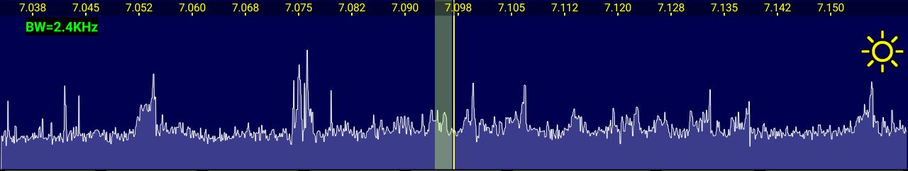
Tuning using the waterfall/spectrum
When waterfall or spectrum are active, you can use touch gestures for tuning purposes.
Currently tuned frequency is shown with a vertical yellow line (reticule), and the audio bandwidth with a semi-transparent yellow band. You can directly tap anywhere on the waterfall to tune to that frequency, or to drag the vertical line left or right. When you are close to the desired frequency, use up/down buttons to select the exact frequency. If the frequency step is set to a usual value for the band, UP/DWON buttons will automatically match the step, no matter from which frequency you started. For example, let’s say frequency step is 1KHz and by dragging the vertical reticule you stop on 7.129341. By tapping UP button one time, the frequency will become 7.130 spot on.
You can tab the waterfall using 3 fingers to reset the zoom.
Adjusting waterfall brightness or spectrum minimum level
In the
right part of the waterfall there is a yellow symbol ![]() .
Drag the symbol vertically to adjust waterfall brightness or spectrum minimum
level.
.
Drag the symbol vertically to adjust waterfall brightness or spectrum minimum
level.
Operating the application in Direct CAT mode.
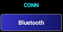
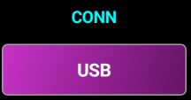
Before operating your own radio in Direct CAT mode, you must set the connection details. Connection mode is already selected during a new profile creation. Check here for more details about how to create a new profile. You can later change the connection mode, if you want, by tapping CONN button and selecting a new one: Bluetooth, USB or pRxTxSever(network).
After you select the desired connection mode, CONN button background will change the color as in the following table.
|
Bluetooth |
USB |
pRxTxServer (Network) |
|
|
|
|
Setting connection mode
To set the parameters for the connection mode, you have to long press on the CONN button in the startup page.
Connecting over Bluetooth
To connect to your radio over Bluetooth, the radio must have Bluetooth CAT capabilities (like Icom IC705), or a Bluetooth CAT module installed (like the very popular ones for Yaesu FT8x7 transceivers).
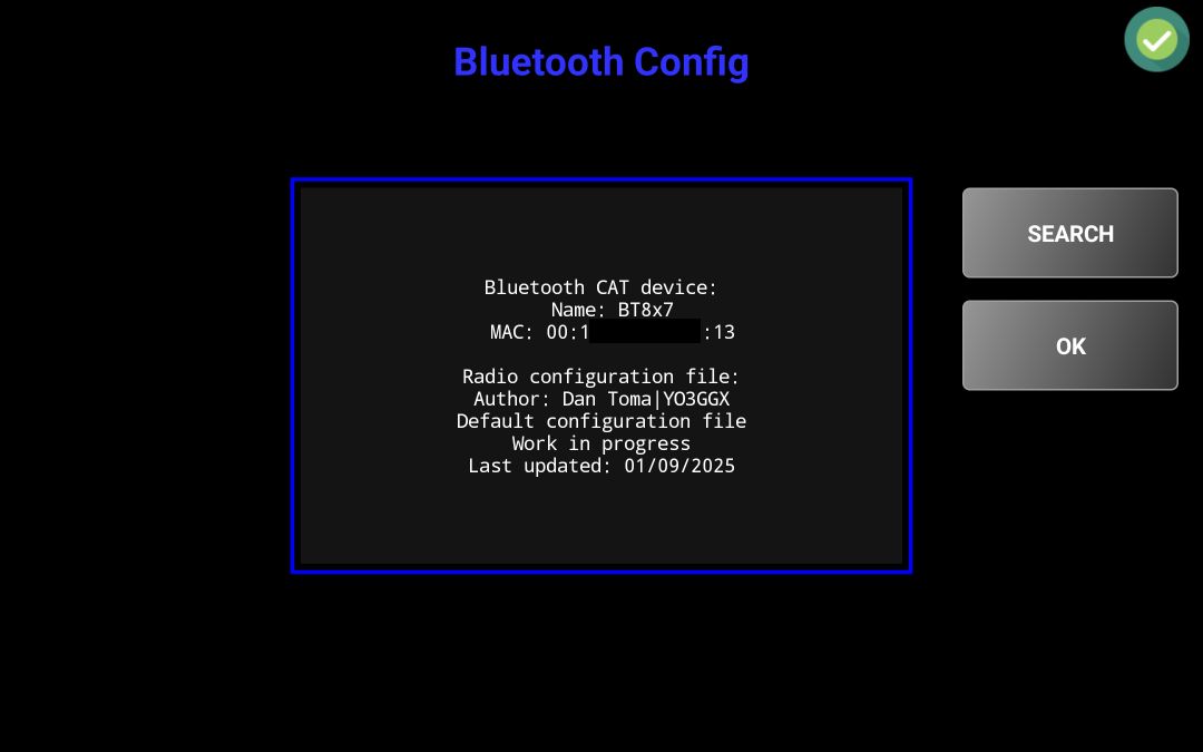
After you long press CONN button in the startup page, Bluetooth configuration page will be open.
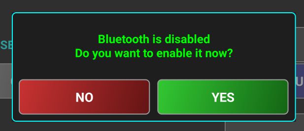
If Bluetooth is not enabled on your device, a message will pop-up.
Tap YES to activate it.
IMPORTANT NOTE:
Bluetooth Discovery requires Location Services to be activated on Android!!!
· Android 6.0 (Marshmallow) and later: Bluetooth scanning (both Classic and BLE) requires ACCESS_FINE_LOCATION or ACCESS_COARSE_LOCATION permissions.
· Android 12 and later: Introduced a separate BLUETOOTH_SCAN permission, but Location Services is still required.
Bluetooth device discovery (Classic Bluetooth) → Requires Location Services ON
Connecting to a known Bluetooth device (paired) → Does NOT require Location Services.
When you scan for Bluetooth devices directly in Android system settings, it works even if Location Services are turned off because:
· System apps have special privileges:
· The Android system itself has privileged access to hardware and does not enforce the same permission restrictions that third-party apps do.
· The Bluetooth settings page is part of Settings (a system app), which can access Bluetooth discovery without requiring Location Services.
· Different permission model for system UI:
· When you scan for Bluetooth devices through the system UI, Android assumes that you, as the user, have explicitly chosen to do so, so it does not enforce location permissions.
· Third-party apps, however, could scan in the background and infer location data, which is why Google enforces location permission for app-based scanning.
Location risk mitigation:
· Google's restriction is primarily about privacy. Since Bluetooth scanning can detect beacons that provide location information, third-party apps must comply with stricter permission requirements.
· The system UI is trusted not to misuse this data, so it bypasses the restriction.
As soon as you pair the Bluetooth device, you can disable Location Services, as is no longer required.
In Pocket RxTx, Location Services ca be used (if user accepts) to auto detect your current location and automatically calculate the grid locator. This is useful for example when searching WebSDR servers on a map and calculate distances between your current location and a selected WebSDR server. If you don’t want to let the application use Location Services, you can still enter manually your current locator.
Tap on SEARCH button to search for nearby Bluetooth devices. As soon as a device is discovered, it is added to the list.
Tap on the Bluetooth device sued for CAT (BT8x7 in the example above) and then on OK. If your device was not found, you can search again by tapping on Search again in the list. Name and MAC address of the selected BT devices is shown.
Click OK when ready. Now you can go and connect to the radio over Bluetooth. Check here for further steps.
Connecting over USB
When you connect your USB CAT interface to the Android device, you are asked to allow the application to access the USB to UART Bridge controller. Tap OK.
NOTE. USB permissions are not persistent between re-plugging a device. Permission is granted only for the current session (i.e., while the device is connected). If the app restarts while the device remains plugged in, you can restore permission automatically without user interaction. However, if the device is unplugged and re-plugged, permission must be granted again. This is a limitation of the Android platform.
A list of USB/Serial devices and interfaces is displayed.
A serial interface can contain multiple devices and multiple interfaces per device. In the example above, a Yaesu SCU-17 CAT interface is connected to the Android device. This contains one device (represented by VID:PID and Name) and two interfaces: Enhanced Com Port and Standard Com Port. First one is used for CAT, the second one for PTT. In the lower part of the screen, you must select the way PTT is triggered: through a CAT command, or through the hardware RTS or DTR pin from the serial interface.
Click OK when ready. Now you can go and connect to the radio over Bluetooth. Check here for further steps.
For the interface selected for CAT, if PTT is defined over CAT or over another interface, you have the option to force RTS and DTR signals to 0 or 1. Some digital interfaces or radios may require setting RTS or DTR to 1 to accept CAT commands.
If an interface is selected only for PTT, RTS and DTR signals will be automatically forced to 0, as soon as you connect to the radio.
NOTE: For debug purposes, you can long press the page title (“Available USB Serial interfaces”) to display a window containing information about all connected USB devices (including audio ones).
Tap on the window to close it.
NOTE: To be able to use a USB cable connection for control, the Android device must support “On the Go” or OTG mode. This changes the Android phone or tablet into being the “host”, the same role that a PC or laptop has and not the slave (dumb device) that it normally operates as. The Android device must be able to send the CAT commands. If your Android device has an older version of Android or one that does not have OTG support, you should look at the network or Bluetooth connection options. To tell the Android device to switch into OTG mode an OTG USB cable or OTG adapter is needed (these are cheap items, but without it the Android device will not be able to communicate over the USB cable with the radio). This applies mainly to the old devices, using a microUSB connector. Another issue for these old devices is that you cannot use OTG and power the Android device from an external device at the same time, so you are forced to use it on battery only.
Most modern Android devices use USB-C and OTG functionality is included. Moreover, using an external USB-C powered hub, you can connect over USB to the radio and power the phone at the same time. Take care to use a powered USB using Power Delivery that can provide power to the host, not only to the connected USB devices. The following were successfully tested by me.
|
|
|

NOTE: Some transceivers require PTT to be controlled over a pin on an accessory socket on the back of the radio. PocketRxTx can only “talk” to serial communications connections that it sees through the USB connector so Interfacing between the radio and the Android device running PocketRxTx will need to take this into account. Several different approaches are taken on different radios to provide computer control, and you will need to refer to your radios documentation to understand what is required to control the radio from a USB computer interface (as is used by PocketRxTx).
In the current version of the application USB CAT interfaces based on the following USB/Serial chips are supported:
FTDI FT230XS UART VID: 0x0403 PID: 0x6015
FTDI FT232R UART VID: 0x0403 PID: 0x6001
RT Systems CT29B VID: 0x2100 PID: 0x9E54
RT Systems USB-62 VID: 0x2100 PID: 0x9E56
Arduino VID: 0x2341 PID: xxxxxx
Teensyduino VID: 0x16C0 PID: 0x0483
Atmel VID: 0x03eb PID: xxxxxx
CP210x UART Bridge VID: 0x10C4 PID: 0xEA60
Prolific PL2303 VID: 0x067b PID: 0x2303
CH340 VID: 0x1A86 PID: 0x7523
STMicroelectronics STM32 VID: 0x0483 PID: 0x5740
Connecting over the Network
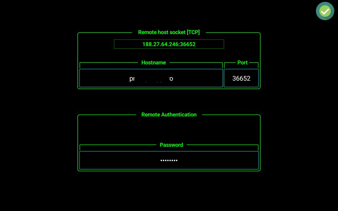
After pRxTxServer connection is selected, long press on the CONN button to configure network settings.

Explanation of the different network configuration fields:
· Network socket [TCP] – This is a read only field, where the socket is displayed if the hostname is correctly converted to IP address.
· Hostname – This is the fully qualified domain name of your router (if connected over the Internet) or the IP address on your local LAN of the PC/Mac/Linux PC/Raspberry PI/Android running the pRxTxServer4 server application. If you connect via the Internet and your server is behind a router, (which it will normally be), enter the external hostname or IP address of the router (the address it has as a device on the Internet). If you are not allocated a “static IP address” or “static hostname” by your ISP, you should look at implementing a dynamic DNS link which will ensure that if your router changes its address on the Internet – the “Dynamic Hostname” automatically goes to the new IP address. In the router you must configure port forwarding to the computer where pRxTxServer4 runs. You must configure port forwarding only for TCP (used for CAT, audio and control). It is simplest if you configure a static IP address within your local LAN for the computer running pRxTxServer4 and this is the IP address that you tell your router to send all data traffic on the port number you chose to.
· TCP Port – TCP port configured in pRxTxServer4 for CAT. The same port number is used for both audio and CAT.
· Password – The connection is secured using a password, that must be entered in the bottom field. All authentication information is encrypted over the network, but after successfully authenticated, the rest of the communication is no longer encrypted. Minimum password length is 6 chars.
· Profile – The profile name from pRxTxServer4 that is used for this connection. This parameter is only available in the PRO version and allows automatic profile switching in the server app when you connect from the client. In this way you can have multiple radios connected to a single server application instance, using separate profiles, but with the same TCP port. Then define for each one a profile in Pocket RxTx4 and easily switch from one radio to another. In the LITE version, you must run several instances of the server application, with different TCP ports assigned for each.
Tap on the green Confirm icon. Now you can go and connect to the radio over the network. Check here for further steps.
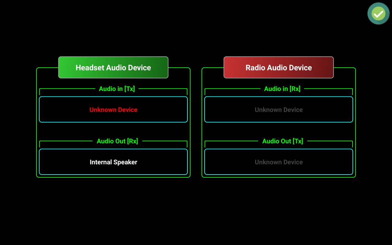
Audio setup
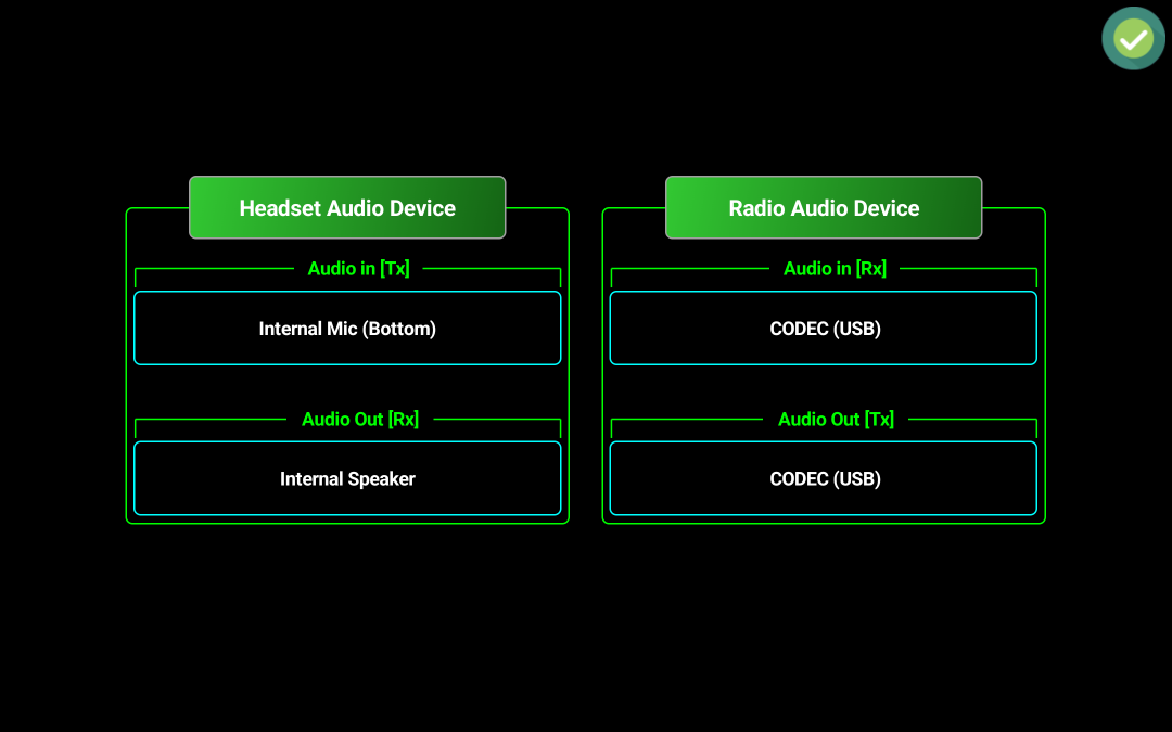
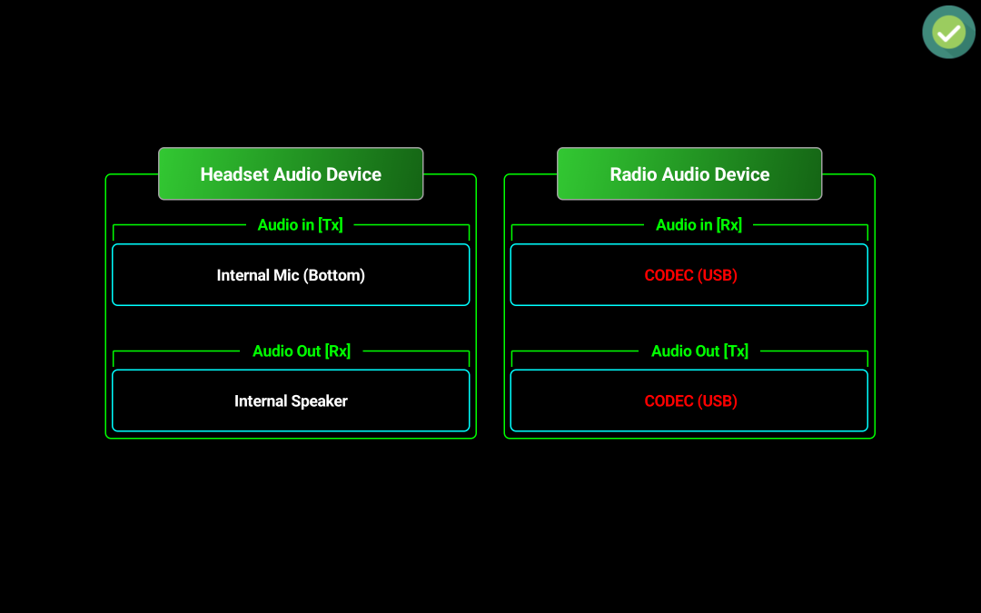
To set up audio, tap on the audio icon in the startup page or in the radio panel. The elements displayed depend on the connection mode. In Bluetooth and USB modes, you can select both headset and radio audio devices, in Server mode you can select only radio audio device and in network or WebSDR mode only headset audio device. Let’s consider USB connection mode is selected.
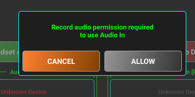
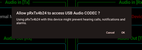
By default, in Direct CAT mode, headset audio is enabled, and Internal Speaker is used as audio output device. Headset audio input is not selected by default, as this requires a specific Android permission named “Record audio”. The user must agree to use an audio input device for Tx. Radio Audio Device is by default disabled, corresponding button is red, showing that. Tap on device button to toggle activation. Buttons will change to green. Then select audio devices one by one. When you select Headset Audio In [Tx] device for the first time, you are asked to provide Record Audio permission for the application.
There are some known limitations:
· Radio audio device must be a USB audio device or Wired Headset if the radio is connected for audio over the smartphone/tablet audio jack (usually no longer available on the newer devices). If you build an audio cable for this purpose, you must take care to adjust audio levels in both directions using some resistive attenuators.
· USB audio headsets are not supported in this connection mode. Android cannot use 2 USB audio devices at the same time.
· This feature is currently fully experimental, and may not work at all on your device, as streaming audio between two locally connected audio devices is not an official feature in Android. In this case, you can use a wireless speaker/mic directly connected to the radio (ex. Over Bluetooth to an iCOM IC705 radio).
NOTE: In the current version of the application, only one way audio is supported when connected over USB or Bluetooth: from radio to your selected headset (Rx). In LITE version, Radio Audio Device cannot be activated.
Tap on the red Unknown Device label to select headset audio in device. You will be prompted to allow this permission. Tap on ALLOW to agree. If you don’t agree, then tap CANCEL, but you will not be able to use Tx audio.
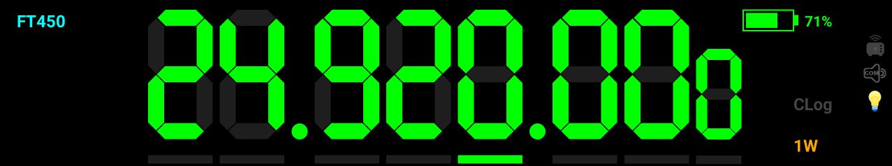
If you agree, from now on you will not be asked anymore for this permission, until a full application reset. Tap again to select headset audio input device.
Select all audio devices by tapping each of them. In the example below, the device is connected to a Yaesu FT450 radio using a SCU 17 CAT/audio interface. You will be asked first to allow us to use the connected USB audio device, in this case SCU17.

Tap OK to confirm.
NOTE: USB permission will be asked again if you disconnect the USB device. This is how Android works, for security reasons. If you keep the USB device connected, you are not asked again, even if you restart the application.
After you select all audio devices, their name will be shown in white.
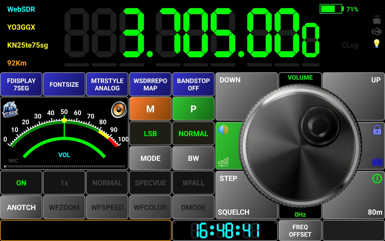
If you enter audio setup and previously selected radio audio device is no longer connected, it will be shown in red.

In the lower part of the audio configuration screen, you can find some more buttons used for low-level configuration of the audio capture device. Can be used to improve audio level or audio devices selection on some specific devices.
![]()
The parameters are:
AGC – microphone audio gain control
NC – Noise cancelation
EC – Echo cancelation.
Audio input type – used to select audio input type. For Android 8 and up, defaults to UNPROCESSED. For lower versions, defaults to MIC.
You can toggle first three but tapping on the corresponding button. Green means that the parameter is activated.
To change Audio input type, long press on the 4th button. You will be prompted to select one of the following types:
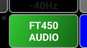
In WebSDR mode, when you enter audio setup, only Headset audio device will be shown. If Server mode Is activated, only Radio audio device will be shown.
If selected Headset audio device is no longer available, a red x will be overlapped over the audio icon in the startup page and radio panel to warn you. The icon is updated automatically if you connect/disconnect the headset.

Radio panel
This is how the radio page looks in Direct CAT mode.

[1] – Currently radio model. When in Mixed Mode, the radio model is followed by the << symbol to show you when current audio is coming from the radio.
[2] – Only in Mixed mode, selected WebSDR server callsign. Again, if currently audio is coming from the WebSDR serever, server callsign is followed by the << symbol.
[3] – A bar graph meter used during Tx, to show you the level of the audio from the microphone. Try to keep this at ~75% for good modulation. If your headset mic does not provide enough level, you have the option to increase mic gain, as described here, but try not to go over 75-80% on the bargraph.
[4] – Frequency display. Dots are presented between 100Hz and 1KHz, between 100KHz and 1MHz and between 100MHz and 1GHz. You can change the frequency in several ways:
· Using the tuning knob. Frequency step in this case is the fine step defined in the radio configuration file (for AUTO) or user selected step (see [20]).
· Using Up/Down buttons. In this case, brute step from the radio configuration file is used (for AUTO) or 10x the fine step selected by the user (see [20]).
· By selecting a specific digit (only for PRO version when 7 segments display mode selected). Tap on a digit you want to increment or decrement. A green bar will be displayed below the digit, to show you that it was selected.
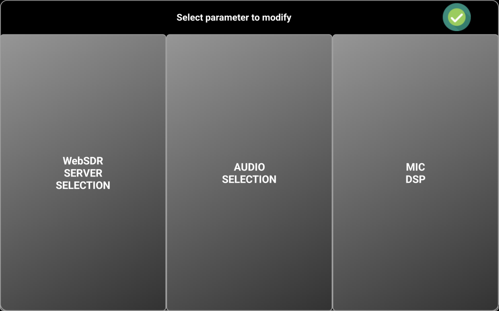
You can now change the frequency with that step using the tuning knob or Up/Down buttons. When ready, tap outside the digits area to clear the selection. The green bar will disappear.
· By direct frequency enter. Long press the frequency display. Tuning knob area will be replaced by a numeric keypad.

Tap the frequency you want (in Hz, KHz, MHz or GHz) and then the respective button. In the example above, 3.705 was typed, then MHz button to enter 3.705MHz. You can clear last digit by tapping BACK button. You can return to the normal radio screen by long pressing the BACK button, if you don’t want to enter the frequency.
When in Mixed Mode, when you tune your transceiver, the WebSDR server will be tuned too, in sync with the transceiver.
[5] – Frequency Down button, used to change the frequency with a negative brute step (usually 10 x tuning knob step).
[6] – When tapping this button, you can adjust the audio level. This is independent from the phone volume physical buttons. The meter scale will change to 0-100%, meter name to VOL and the button background color to green.

The black label in the top of the tuning knob will show current mode as VOLUME. Use the tuning knob to adjust the audio volume. When ready, tap the button again to return to normal operation.
[7] – Here the current battery level is displayed, in the PRO version only. In the LITE version, this symbol is grayed out.
[8] – When Server Mode is activated, this icon becomes green.
[9] – When the radio model is (tr)uSDX or uSDX and audio over CAT is activated, this icon will be on. Check here for more details about how to use audio over CAT with these transceivers.
[10] – This icon will be on when Always ON mode is activated. See here for more details about what this mode means and how to activate it.
[11] – Clog symbol is on when a call record is activated. See here for more details about Call Logging.
[12] – Frequency Up button, used to change the frequency with a positive brute step (usually 10 x tuning knob step).
[13] – Here you can see the current function for the tuning knob (TUNING, VOLUME or F-OFFSET).
[14] – This button has 2 functions. When two icons or words are on a button, lower one means the function for tap and the upper one the function for long press.
When you long press on this button, you will toggle the LOCK function for the whole graphical interface. If you tap this button, you activate/deactivate the waterfall, only when in Mixed Mode. This will be the waterfall for the associated WebSDR server.
On top
of the waterfall is the frequency scale. In the top left you can see current
bandwidth. In the right, there is the symbol ![]() .
Drag this symbol vertically to adjust waterfall brightness according to your
preferences. Drag it in the upper direction to increase the brightness or drag
it down to decrease it.
.
Drag this symbol vertically to adjust waterfall brightness according to your
preferences. Drag it in the upper direction to increase the brightness or drag
it down to decrease it.
You can use the associated WebSDR waterfall, even if reception is selected from the radio, so it will behave as if your radio is a SDR one with Waterfall functionality.
[15] – Long press this button to connect to the radio (ON/OFF button). When in Mixed Mode, the connection to the associated WebSDR is initiated too. When already connected, long press this button to disconnect from the radio. If you tap this button when connected to the server, you can select the band from the ones available for the current radio. Currently selected band is marked in Green.
[16] – This is the tuning knob but can be used for volume adjustment or to set frequency offset too.
[17] – This is the PTT button.
NOTE: When the application is in compact mode, this button is no longer available, so you must define a hardware key for PTT, as described here.
[18] – Only when Mixed Mode is activated and you select WebSDR reception, here will be displayed the frequency offset for that WebSDR server and band (defaults to 0). Check here to see how to adjust frequency offset for the WebSDR server. When radio audio is selected, it is not used.
[19] – When in Mixed Mode, this button is used to toggle between Radio and WebSDR audio.
|
WebSDR audio |
Radio audio |
|
|
|
[20] – When tapping on this button, you control the last radio parameters from the FAVORITES list. In fact, this is the 8th option button, a special one as it does not have an associated label. Use it for parameters with a single state (for example TUNE) or with ON/OFF states. When the parameter is ON, button background is green, when it is off it is gray.
Long press on this button to set the frequency step for the tuning knob. A selection panel will be displayed.

When AUTO mode is selected, the frequency step defined in the radio configuration file is used. For more details about the radio configuration file, tap here.
[21] – An UTC clock is permanently visible in this area. If you tap on the UTC clock when connected to the WebSDR server, call logging is activated. Tap here for more details about call logging.
In top left and top right of the UTC clock area there are two small virtual LEDs. The left one will flash when data is transmitted from the application to the radio, the right one when data is received from the radio.
[22] – This button shows “SET” when disconnected from the server and “P” when connected for the server. Tap on this button when disconnected from the WebSDR server to access some functions.
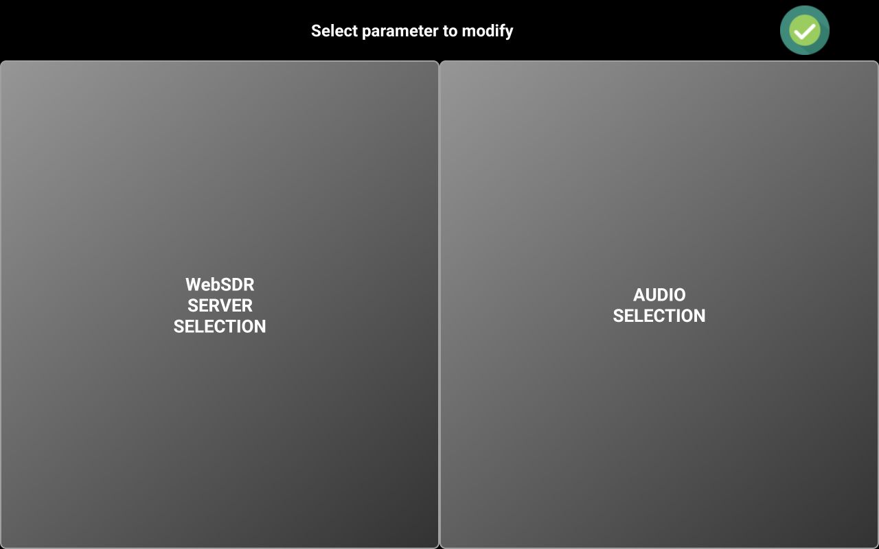
As there is no dedicated icon for the WebSDR server, when in Mixed Mode, you can select the WebSDR server using WebSDR SERVER SELECTION button. Server selection is performed as explained here.
Check [24] for more details about selecting the audio device. If in Mixed Mode, you will have access to the Mic DSP too.

NOTE. MIC DSP cannot be used if headset audio in device was not yet selected, so you will receive a pop-up message stating this. More about Mic DSP in the dedicated chapter here.
[23] MEMORY button is used to recall a memory location or to save current settings to a new memory location. To save current settings to a new memory location, long press on the M button.
You will be prompted to select one of the 99 available memory locations (in 3 pages).
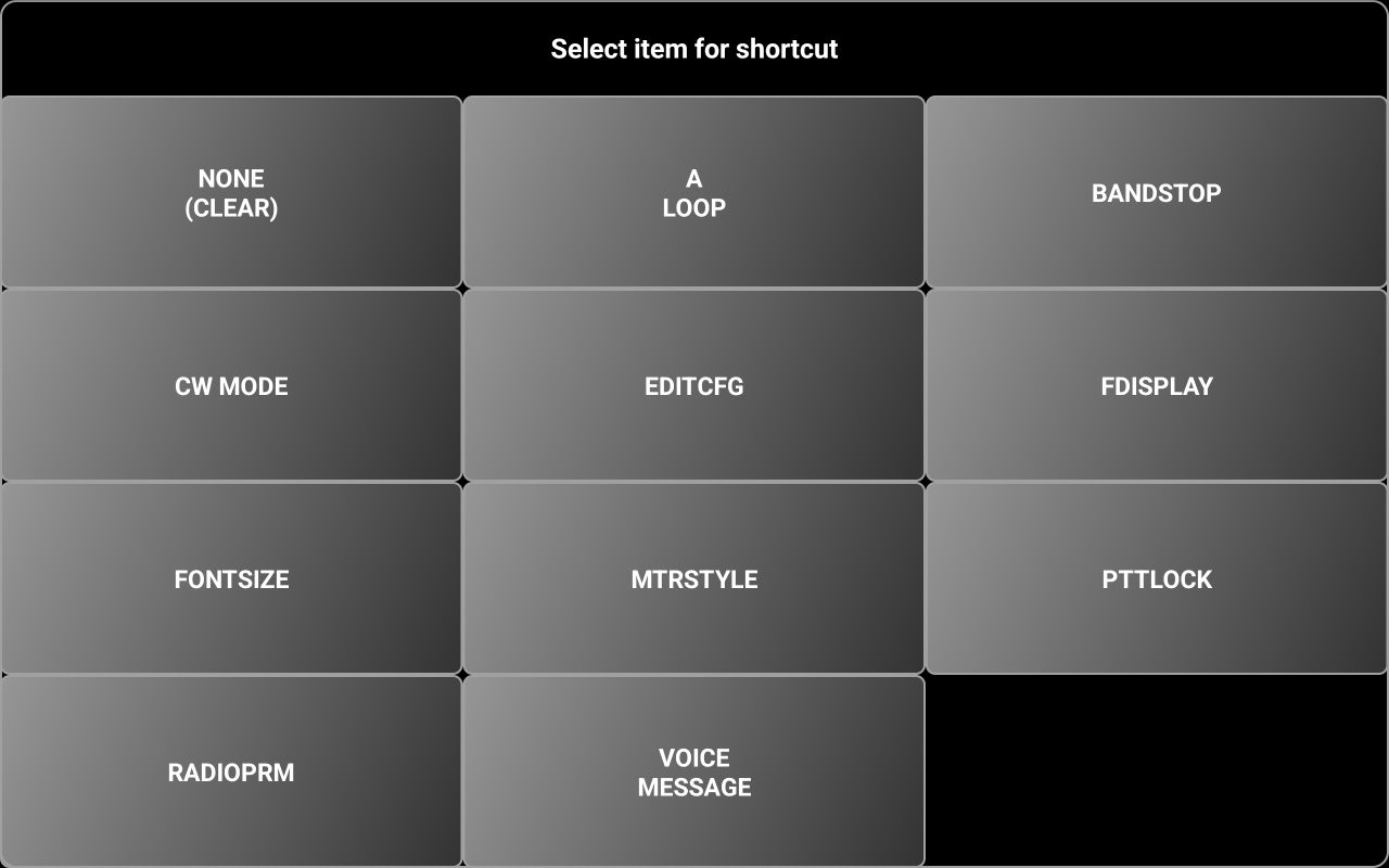
NOTE: In the LITE version, only 16 memory locations are available.
To go to the next page of 33 locations, tap on >>. To go to the previous page with 33 locations press <<. Tap on the memory location you want to use.
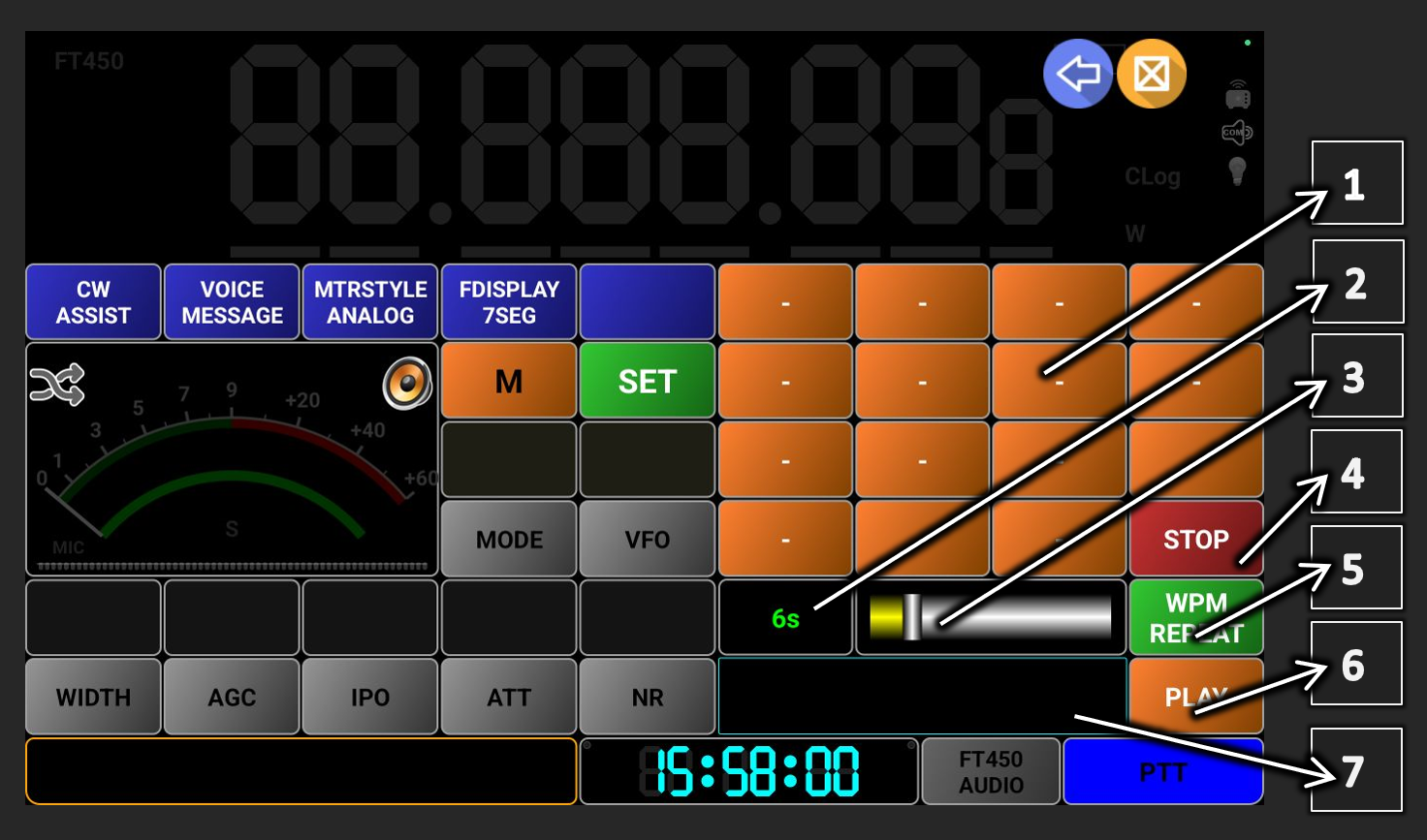
You will be prompted to enter a name for the memory location (7-8 chars maximum) and a description (optional), separated by a comma. Tap on OK when ready. A pop-up will confirm that the memory location was saved. All defined memories are now part of the profile file, no more use dedicated files. In the LITE versions, all up to 16 memories are saved in the global app configuration file.
To recall a memory location, tap on M button and then select memory location you want to recall. Only defined locations will be shown in a selection panel.
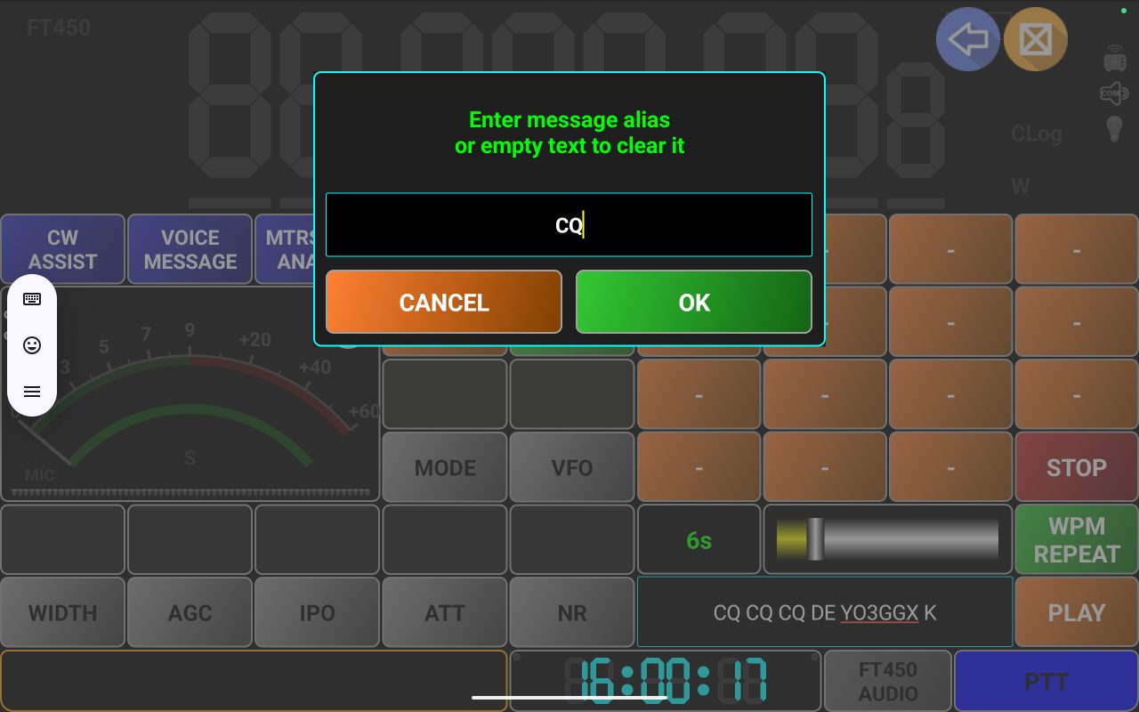
All saved parameters will be loaded and the radio set accordingly. If a description was saved, the text will appear as a 2s pop-up on the screen. If in WebSDR mode and selected WebSDR server provides server-based memories, these will be displayed in green.
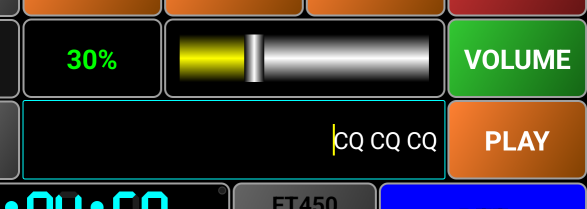
Server-based memories cannot be removed.
[24] Tap here to set up and select audio devices, as described here. This icon represents the selected headset audio out device. If the selected audio device is not currently connected, an X will be shown over the audio device icon. Tap here for more details about the audio icons.
[25] – This is the status info area. Here different messages will be displayed and when Waterfall or Spectrum are visible (covering the main frequency display), tuned frequency will be displayed here.
![]()
The standard functionality of the frequency display area will be available here too (digit selection, direct frequency entry through long press).
[26] – There are 8 parameter buttons predefined in the radio configuration file, in the FAVORITES line, in the following order:
· 0 and 1 -> the two below M and P buttons.
· 2-6 -> below the meter and first two
· 7 -> lower left corner of the tuning knob area.
For the first 6 parameters, there is a label on top, displaying parameter value.
You can reassign any of the first 7 buttons to another parameter, by long pressing on it. A selection panel will allow you to select another parameter to be assigned to that button, or to reset to the ones from the radio configuration file.
[27] – Here you can see the current value for the parameter from the button below.
[28] – The meter can be a bar graph or an analog style one. In the LITE version only the bar graph type is available. Different scales are available for SMETER, VLTMETER, SWRMETER, PWRMETER, ALCMETER, MODMETER, AUDIO VOLUME. You can tap on the meter image to select the meter for Rx (SMETER or VLTMETER). Long press on the meter image to select the meter for TX (SWRMETER, PWRMETER, ALCMETER, MODMETER). Only the meters with a valid definition in the radio configuration file appear in selection.
[29] – This icon shows status for the Mixed Mode, as in the table below
|
|
Mixed Mode is not available (LITE version) |
|
|
Mixed Mode OFF |
|
|
Mixed Mode ON |


[30] – You have 5 blue user programable buttons. When you run the application for the first time, all 5 are empty (nothing assigned to them). To assign a function to them, long press on a blue button. You will be prompted to select what function to assign. These are the options available in Direct CAT mode.

· NONE (CLEAR) tap here if you want to remove a previous assignment.
· A LOOP – Audio Loop mode. Click here for more details about how to use Audio Loopback functionality.
· BANDSTOP – used to select IARU region for band limits. More details here.
· CW MODE – used to activate CW ASSIST functionality. More details here.
· EDITCFG – used to access the simple text editor for the radio configuration file. More details here.
· FDISPLAY – used to select between 7 segments and legacy frequency display. This is available only in the PRO version. More details here.
· FONTSIZE – used to adjust application font size and display corners radius. More details here.
· MTRSTYLE – used to select meter type (ANALOG or BARGRAPH). This is available in PRO version only. More details about the meter formats here.
· PTTLOCK – used to toggle PTT, if you want to have the hands-free during Tx.
· RADIOPRM – by tapping here, a selection panel will open with all available radio parameters. Click on the one you want to assign to the button.
· VOICE MESSAGE – access voice message recording and playback. More details about voice messages here.
[31] – When Mixed Mode is active, the distance between your current location and the selected WebSDR server is displayed here in orange color. Depending on the UNIT selection from the menu (see here), the distance is in km or in miles.
[32] – Only in Mixed Mode, selected WebSDR server locator (6-10 chars).
[33] – Here is displayed the maximum Tx power currently set for the transceiver. You can tap on this icon to directly access TXPWR setting, without going through the parameters panel.
NOTE. Some radios use different power settings per band or group of bands (ex. HF/6m/4m/VHF/UHF). Here the power setting for the current band/frequency will be displayed.
Mixed Mode (PRO only)
This allows you to use your transceiver together with a selected WebSDR server. To toggle mixed mode, you have two options (only when disconnected from the radio):
· Tap on the dedicated icon when not connected to the radio (Only in normal display mode).
· Long press on the green SET button and then tap Mixed Mode button (in both normal and COMPACT modes).
Current Mixed Mode status is represented by the icon image.
|
|
Mixed Mode OFF |
Mixed Mode ON |
Mixed Mode unavailable |
|
Normal display |
|
|
|
|
Compact display |
|
|
|


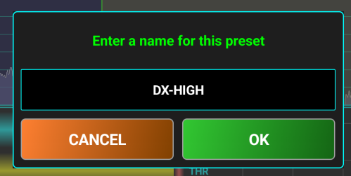
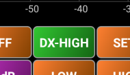
When Mixed Mode is activated and you connect to your own transceiver, a connection to the WebSDR is automatically started. Both are kept in sync with frequency and mode when tuning. If there is a small frequency shift for the selected WebSDR server, you can use Frequency Offset feature as described here to keep the frequency in perfect sync. When in Rx, you can select between WebSDR and your own radio audio, in real-time, bu tapping the button Moreover, you can benefit from the WebSDR waterfall/spectrum to tune your own transceiver. If waterfall or spectrum are activated, it will remain active even when you select audio from your own radio. It is like you are transforming your radio into a SDR radio.
You can switch between radio and WebSDR audio using the dedicated button. This button position on the screen depends on device type, size, orientation, or compact/normal display mode. Tap to toggle Rx between the selected WebSDR server and your own radio. When Rx is from WebSDR server, you can long press the button to activate frequency offset mode. Tap again to return to normal operation for the button. More about setting WebSDR frequency offset here. Possible states for this button are presented in the following table.
|
Mixed Mode OFF |
Mixed Mode ON |
Frequency offset mode |
|
|
Rx from WebSDR |
Rx from own radio |
||
|
|
|
|
|
If Audio from the WebSDR server is selected, it will not be muted during Tx, so you can hear your voice as it is received on that server (in real-time), if the server is in your Tx coverage area.
NOTE:Audio from WebSDR is disabled when in Tx if internal device speaker or earpiece are used as audio out device. This is to prevent audio loops. You must use a headset.
For more details about operating in WebSDR mode, click here.
Automatic CW Keyer (PRO only)
The application can automatically send CW messages that are directly entered as text or from up to 15 pre-saved message memories. The Automatic CW Keyer can be accessed by assigning this function to one of the 5 blue user defined buttons, as described here, or by long pressing on the green SET/P button and then selecting CW ASSIST.
Button name is CW ASSIST and can be used as a toggle for the CW ASSIST panel ON/OFF.
Automatic keyer can be accessed even when not connected to the radio, allowing you to define up to 15 messages and to play them locally. When you tap CW ASSIST button, tuning knob panel is replaced by the CW ASSIST panel.
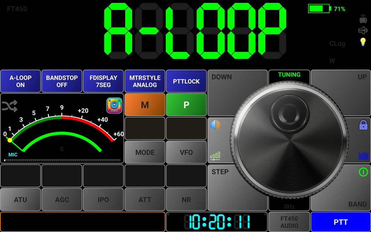
[1] – 15 orange buttons used to save and then to directly access CW messages.
[2] – When you activate CW ASSIST, this will show current message repeat interval in seconds. When setting Words Per Minute [WPM] transmission speed, will show current WPM value (see [5] button description below). During the message playback, this label will show current message volume, from 0 to 100%.
[3] – Use the slider to adjust transmission speed (WPM between 5 and 60) or auto-repeat interval (3-20s, default value is 6s), or WPM (between 10 and 40WPM, default is 20WPM) - see [5].
[4] – Tap this button to immediately stop message transmission (when connected to the radio) or playback (when offline).
[5] – This button has 3 functions. When you enable the CW ASSIST mode, tap this button to toggle auto message repeat ON or OFF. When ON, button background changes to green and current repeat interval in seconds is shown in [2]. You can use the slider [3] to adjust the message auto-repeat interval from 3 to 20s. Long press on this button to activate WPM setting. Label [2] will show current WPM value and you can use the slider [3] to adjust it between 10 and 40WPM. To return to REPEAT ON/OFF mode, tap this button when in WPM mode.
[6] – When offline, tap this button to play locally current message entered in textbox [7]. When connected to the radio, tap this button to transmit the same message.
[7] – Enter here the text you want to assign to an orange button or to transmit/play it directly.
To assign a message to one of the orange buttons, enter the text in [7] and long press the orange button you want the message to be assigned to. Text can be entered in both lower and upper case.
You will be prompted to enter an alias for the message.
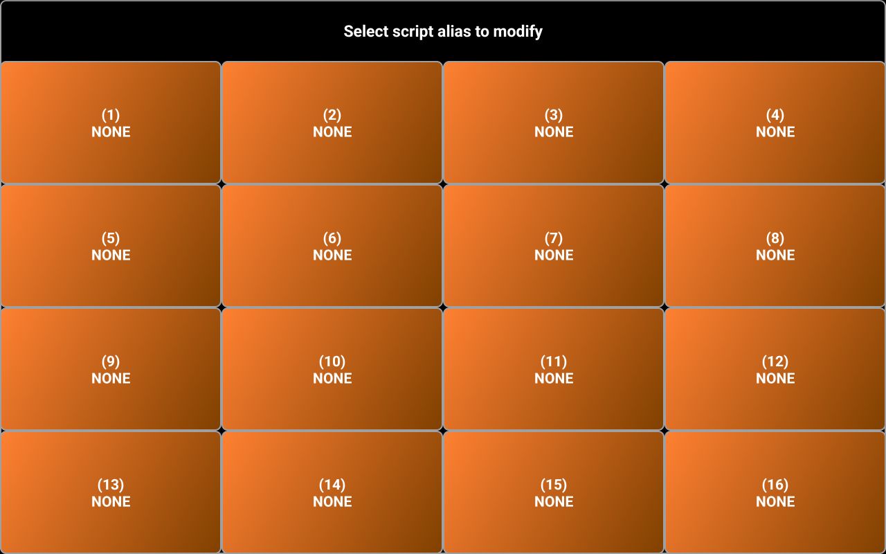
Enter the alias and tap OK. The button name will be set to the alias. Now you can tap the newly defined orange button to play the message. During the message playback, you can adjust the audio volume using the same slider [3]. WPM/REPEAT button name will change to VOLUME during playback.

As message is played, corresponding letters are shown one by one in the textbox [7]. You can stop playback at any time, by tapping the red button STOP ([4]).
After the message is played/transmitted or stopped, the WPM/REPEAT button returns to normal functionality.
You can play/transmit the message in the textbox directly, without assigning it to an orange button by tapping orange PLAY button after you enter the text in the textbox [7].
Transmitting CW messages using CW ASSIST requires a CAT interface that allows you to use different signals for PTT and keying, for example RTS for PTT and DTR for keying, like the Yaesu SCU-17 or internal USB CAT interface in some other radios. You may need to configure your radio for this purpose.
If you connect directly to your radio over USB (Bluetooth connection is not supported for CW ASSIST), you must configure the signal used for PTT (RTS or DTR). CW ASSIST does not currently work if you select PTT over CAT. If you select RTS for PTT, then DTR will be used for keying. If you select DTR for PTT, RTS will be used for keying.
If you connect over the network to pRxTxServer4, same configuration applies for the server side. See here for more details about how to configure PTT in pRxTxServer4.
Transmitting a CW message by direct text entry
Enter some text in the black textbox [7] and then tap PLAY button.
Transmitting a CW message by recalling a pre-stored message
If you assigned a CW message to one of the 15 orange buttons, just tap on it to transmit/play that message.
Deleting a saved CW message
To delete a CW message assigned to one of the 15 orange buttons, long press on that button. When you are asked to enter an alias, leave the textbox empty and tap OK. You will be prompted to confirm deletion.
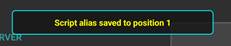
Tap OK.
Voice Messages (PRO only)
You can record and then play or transmit voice messages. Messages can be generated using Android Text-to-speech (TTS) embedded features, instead of recording. The TTS language is the one set in the Android system configuration.
The Voice Messsages feature can be accessed by assigning this function to one of the 5 blue user defined buttons, as described here, or by long pressing on the green SET/P button and then selecting VOICE MESSAGES.
Button name is VOICE MESSAGE and can be used as a toggle for the Voice Messages panel ON/OFF.
Voice messages can be accessed even when not connected to the radio, allowing you to define up to 15 messages and to play them locally.
When you tap VOICE MESSAGE button, tuning knob panel is replaced by the Voice messages panel.
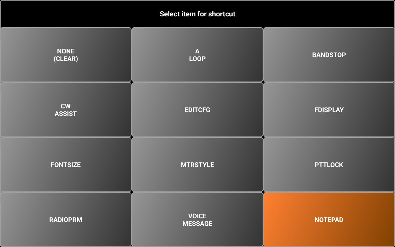
[1] – 15 orange buttons used to save and then to directly access voice messages.
[2] – When you activate Voice messages, this will show current message repeat interval in seconds. During the message playback, this label will show current message volume, from 0 to 100%.
[3] – Use the slider to adjust auto-repeat interval (3-20s, default value is 6s), or to adjust audio volume when playback the voice messages locally.
[4] – Tap this button to immediately stop message transmission (when connected to the radio) or playback (when offline).
[5] – Tap this button to toggle auto message repeat ON or OFF. When ON, button background changes to green and current repeat interval in seconds is shown in [2]. You can use the slider [3] to adjust the message auto-repeat interval from 3 to 20s.
[6] – When offline, tap this button to play locally current message entered in textbox [7] or saved to a voice message button. When connected to the radio, tap this button to transmit the same message. Long press this button to save the voice message entered in the textbox [7]. TTS engine is used to convert text to voice.
[7] – Enter here the text you want to assign to an orange button or to transmit/play it directly.
Creating a voice message using Text-to-speech engine
To assign a message to one of the orange buttons, you can record it or use TTS engine.
The language and voice used by the TTS engine are configured through Android settings (normally system locales are used). The exact way to do it depends on the device and Android version. To use TTS engine, enter the text in textbox [7] and long press the orange SAVE/PLAY button.
You will be prompted to enter the message button number (from 1 to 15) and an alias for that message, comma separated.

When ready, tap OK. The label of the selected button will be set to the voice message alias.

Now, when you tap on that button, if you are not connected to the radio, the message will be played locally. If connected to a radio, the message will be played locally and transmitted at the same time. PTT is automatically activated before sending the message and released after the voice message was sent, so you don’t need to push it yourself. If REPEAT is activated, message is automatically repeated at the defined interval. PTT is automatically released between transmissions, to allow receiving a potential answer to your call.
Recording a voice message
To record a voice message, long press on an orange button. If respective button has a message already assigned, that message will be overwritten by the new one. You will be prompted to enter an alias for the message.
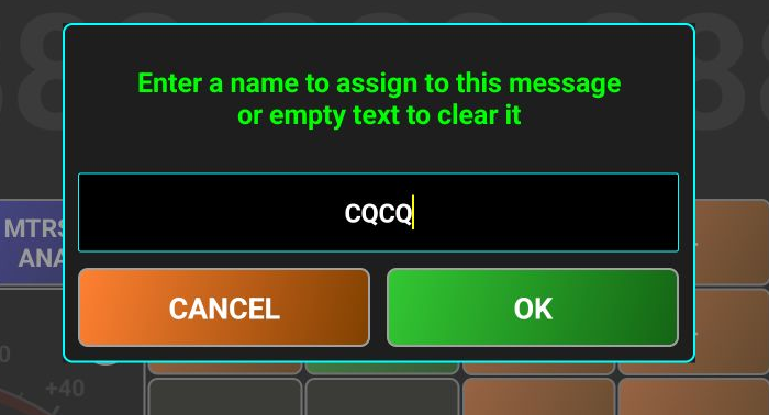
After you enter the alias, tap OK. Two consecutive pop-up messages will be displayed.
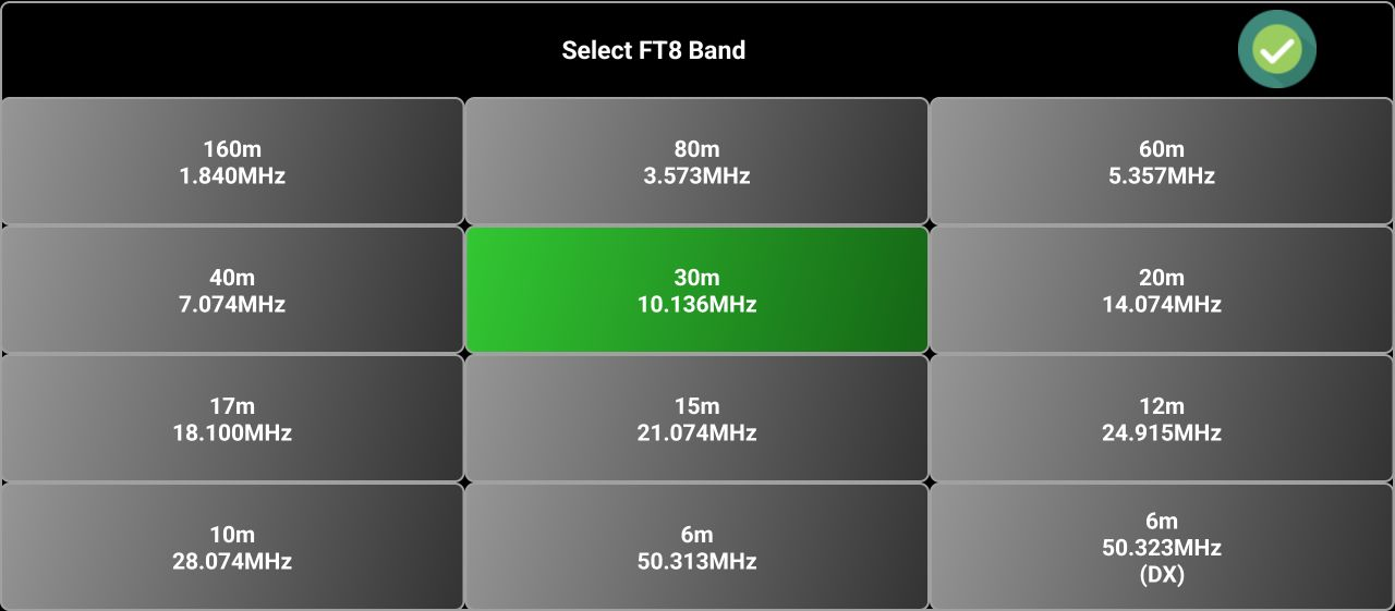

As soon as you hear the tone, start speaking into the microphone. When voice message is finished, tap the red STOP button. Two short tones will confirm that the recording was stopped. You can now play the message locally, when offline, by tapping SAVE/PLAY button. If connected to the radio, the message will be transmitted too, at the same time. PTT is automatically activated before sending the message and released after the voice message was sent, so you don’t need to push it yourself. If REPEAT is activated, message is automatically repeated at the defined interval. PTT is automatically released between transmissions, to allow receiving a potential answer to your call.
Transmitting a voice message by entering text
You can play or transmit a voice message by just entering a text in the textbox [7] and tapping SAVE/PLAY button. TTS engine is used to convert text to voice.
Transmitting a voice message by recalling a pre-stored voice message
If you assigned a voice message to one of the 15 orange buttons, just tap on it to transmit/play that message.
Deleting a recorded voice message
To delete a voice message assigned to one of the 15 orange buttons, long press on that button. When you are asked to enter an alias, leabe the textbox empty and tap OK. You will be prompted to confirm deletion.
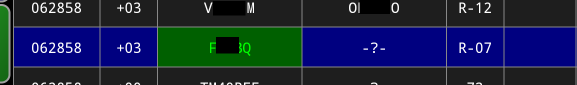
Tap OK.
Mic DSP
The Microphone DSP is based on a 4-bands compressor and is available only in Direct CAT mode.
You can change the cross-over frequencies between the 4 bands, in the interval 0-3000Hz. For each band, a set of specific parameters are defined:
· P/R - Peak vs RMS sensing
o Range: 0.0 to 1.0
o Explanation: A peak-sensing compressor responds to the peak level of the signal. While providing tighter peak level control, peak level sensing does not necessarily relate to human perception of loudness. Applying a power measurement function (RMS) on the input signal before comparing its level to the threshold, a more relaxed compression is produced, that more closely relates to human perception of loudness. You can set any point between the two extremes. 0.0 use only Peak, 1.0 only RMS.
· THR - Threshold [dB]
o Range: -40.0 dB to 0.0 dB
o Explanation: Determines the level at which compression starts. Lower values mean more compression applied to quiet sounds, while higher values compress only loud peaks.
· ATK - Attack [ms]
o Range: 1.0 ms to 400.0 ms
o Explanation: Defines how fast compression engages once audio exceeds the threshold.
o Short Attack (1-10ms) → Fast response for transient-heavy sounds (e.g., percussion)
o Long Attack (50-100ms) → Smooth compression for vocals and sustained sounds
· RLS - Release [ms]
o Range: 10.0 ms to 500.0 ms
o Explanation: Determines how quickly compression stops after the signal drops below the threshold.
o Short Release (10-50ms) → Best for fast, punchy compression (drums, radio voice)
o Long Release (200-500ms) → Best for gradual, smooth compression (music, speech)
· RTO - Ratio
o Range: 1.0 to 20.0
o Explanation: Controls how much compression is applied once the threshold is exceeded.
o (No compression)
o 4.0 (Moderate compression)
o 10.0+ (Heavy limiting)
· KNE - Knee [dB]
o Range: 0 dB to 10.0 dB
o Explanation: This controls whether the bend in the response curve between below threshold and above threshold is abrupt (hard) or gradual (soft). A soft knee slowly increases the compression ratio as the level increases and eventually reaches the compression ratio set by the user. A soft knee reduces the potentially audible transition from uncompressed to compressed and is especially applicable for higher ratio settings
· MKG - Make-up Gain [dB]
o Range: 0.0 dB to 36.0 dB
o Explanation: Because a compressor only reduces the level of the signal, the ability to add a fixed amount of make-up gain at the output is usually provided so that an optimum output level is produced.
· IGN - Input Gain [dB]
o Range: 0.0 dB to 30.0 dB
o Explanation: You can increase the level at the compressor input
Mic DSP can be accessed to it in multiple ways:
· Long tap the audio icon.
· When not connected to the radio, tap on the green SET button and then on MIC DSP.
· When connected on the radio, tap on the green P button and then on MIC DSP.
![]() A dedicated panel will be displayed.
A dedicated panel will be displayed.
[1] – Frequency scale (from 0 to 3000Hz).
[2] – Audio Spectrum. You can drag the separation frequencies (vertical, colored bars) to adjust them. The currently selected band is marked by a semi-transparent overlay, and the band name is displayed in the background of the black compressor graph: SUB, LOW, MID or HIGH. The seven compressor parameters (Peak/RMS, Threshold, Attack, Release, Ratio, Knee and Make-Up Gain) are defined per band.
[3] – Here is displayed the compressor curve for the selected band. The app does not allow us to set parameters that can generate an output greater than 0dB, to prevent supra-modulations.
[4] – Tap this button to set compressor to OFF.
[5], [6], [7], [8] – 4 presets, to be used to save user defined compressor parameters sets. After you set the desired parameters, long press one of the SET buttons to save settings.
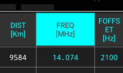
Enter a name for the preset (min. 3 chars) and tap OK. Button background will go green, and the preset name is displayed.
![]()
To clear a preset, long press again on the button, do not enter any name and tap OK.
[9] – This is the PTT button. You can use it to transmit, or in Audio Loopback mode to test your own modulation.
[10] – Tap on this button to exit Mic DSP.
[11] – This is a hard coded preset with high compression.
[12] – This is a hard coded preset with low compression.
[13] – The filters used to separate the 4 bands can have a slope of 122dB or 24dB. Toggle between the two using this button.
[14] – This is a meter showing current audio level at the filter output
[15] – IGN – Input Gain (see description at the beginning of this chapter).
[16] – MKGMake-Up Gain (see description at the beginning of this chapter).
[17] – KNE – Knee (see description at the beginning of this chapter).
[18] – RTO – Ratio (see description at the beginning of this chapter).
[19] – RLS – Release (see description at the beginning of this chapter).
[20] – ATK – Attack (see description at the beginning of this chapter).
[21] – THR – Threshold (see description at the beginning of this chapter).
[22] – P/R – Peak/RMS (see description at the beginning of this chapter).
Transceiver configuration files
For each transceiver in direct CAT mode, two files are required:
· A configuration file with the filename brand_model.radio4 (ex. yaesu_ft450.radio4)
· A 480x320 png image representing the radio (with a transparent background), with the filename
· radiomodel.jpg (ex. ft450.jpg)
All filenames are lowercase.
Currently 3 main CAT protocols are supported:
· Byte based, with command prefix and suffix (iCOM, Xiegu, etc.).
· Byte based, no prefix or suffix, fixed length (Yaesu FT100/817/818/857/897, UBITX and other clones).
· String based, using only a suffix (rest of Yaesu radios, Kenwood, Elecraft, uSDR, etc.)
NOTE: You can edit the transceiver configuration files directly on your device, as described here, or after exporting the files to a PC running pRxTxServer4, as described here.
The file is based on the following general structure for each line: <parameter>=<values>.
NOTE: Anywhere in the file you can enter comments by starting the line with the “;” char.
The radio configuration file contains the following sections: the header, SET commands (used to set radio parameters), READ commands (used to read a parameter value from the radio), PATterns (used to define how to interpret radio answer for a READ command), and CALibration info (used to calibrate the following meters: SMETER, SWRMETER, PWRMETER, ALCMETER, MODMETER and VLTMETER. Some of them may not be available for a specific radio.
The header – general info about the radio.
This section is common for all radios. The example is for Yaesu FT450 (comments from the file are excluded), but the format is similar for all radios, only the values may be different. For each line, the explanation is presented with green text.
TIMESTAMP=3/09/2025|19:46:00
The timestamp in the format MM/DD/YYYY|HH:MM:SS when the configuration file was updated last time in the central repository. If you edit the file locally, you must update this manually.
DESCRIPTION=Default configuration file|Work in progress
Description for the current file/version, to be displayed in the application startup page info box. ‘|’ character will be replaced with new line (cr) when displayed, so in the example above, description will use 2 lines.
AUTHOR=Dan Toma|YO3GGX
The name of the configuration file author. Some of the configuration files may be created by the application users and published in the central repository. You can split the text on 2 lines, if you want, using ‘|’ character.
VERSION=4
PocketRxTx version 4 use version 4 configuration files. This value must not be changed, otherwise the application may not work as expected.
BRAND=YAESU
The brand of the currently connected radio, in uppercase.
MODEL=FT450
The radio model, in uppercase.
PIC=ft450.png
The name of the file contains the radio picture. Must be in PNG format, with transparent background
SIGRADIOS=$1gG49@A10XsG
A signature is used for file validation. Do not change it.
DEVICEMODE=1
This is for future use. Device mode can be:
1 - standard CAT, no decoding inside this app, possible waterfall through serial CAT (ex. IC7300, IC705), audio DSP
3 - audio IQ based radios (Malahit DSP, SoftRock, etc.), decoding inside this app, CAT commands still supported for special functions
4 - RTLSDR or RSP1A devices over standard rtl_tcp/rsp_tcp
5 - RSP devices over extended rsp_tcp
6 - IQ wave file (local or remote through http(s)
7 - (tr)uSDX, use audio in/out over serial port
RXONLY=0
This parameter is 0 for radios with both Tx and Rx and 1 for receivers only.
USERGUIDE=https://www.yaesu.com/downloadFile.cfm?FileID=15340&FileCatID=158&FileName=FT%2D450D%5FOM%5FENG%5FEH024H258%5F1901L%2DLS%2D1.pdf&FileContentType=application%2Fpdf
This is an URL to be used for radio user manual. It can be a HTML page or a PDF file.
CATPROTOCOL=https://www.yaesu.com/downloadFile.cfm?FileID=13311&FileCatID=158&FileName=FT%2D450D%5FCAT%5FOM%5FENG%5F1710%2DB.pdf&FileContentType=application%2Fpdf
This is an URL to be used for radio CAT protocol document. It can be an HTML page or a PDF file.
RADIOADDRESS=
This parameter is used only for iCOM and other radios sharing a similar CAT protocol. Radio address must be a 2 chars HEX value (ex. A4). If your radio does not yet have a configuration file available in the central repository, you can start with a file from another similar iCOM radio and edit the Radio Address value. This can be edited directly from the application too.
FRANGE=30000-56000000
This parameter defines the frequency range covered by the radio (in Hz). If multiple frequency segments, then separate them by comma, like f1-f2,f3-f4,f5-f6,…
FSTEP=0.5/0.01=100000-87499999,100/5=87500000-107999999,1/0.01=108000000-136999999,25/0.01=137000000-137995000,6.25/0.01=138000000-173999999,25/0.01=174000000-215999999,12.5/0.01=216000000-224999999,12.5/0.01=225000000-469999999,25/0.01=470000000-1300000000
Here you can define default frequency step for each frequency range. Step is in KHz, frequency range is in Hz. Brute step is used for UP/DOWN buttons, fine for the tuning knob. The format is:
<brute_step1>/<fine_step1>=<freq_interval1_min>-<freq_interval1_max>,<brute_step2>/<fine_step2>=<freq_interval2_min>-<freq_interval2_max>, ...
PREFIX=
For the radios using a prefix for the CAT commands, enter the prefix in hexadecimal here, even the protocol is string based (chars converted in hex values). Leave it empty if prefix is not used.
SUFFIX=3B
For the radios using a suffix for the CAT commands, enter the suffix in hexadecimal here, even the protocol is string based (chars converted in hex values). In the example here, 3B is the ‘;’ character.
LENGTH=0
For the radios using a fixed length cat command (like Yaesu FT8x7), put the command length here (in bytes). For variable length commands, use 0.
INTERVAL=0
For unreliable links, or when connected over USB using a low BaudRate (like 9600), you can increase the interval between 2 successive CAT commands, using a value greater than 0 for INTERVAL. This can prevent overlapping between successive commands answers from the radio. The value is in ms. Use 0 for the fastest possible communication.
TUNEPWR=10
The power (in W) to be used during antenna tunning. Will be used by the SWR measuring routine, in a future version.
TUNEMODE=FM
The mode to be used for antenna tunning. Not used in the current version.
CWKEY=2
When using Automatic CW Keyer feature (as described here), you can specify the CAT port to be used for keying and if a PTT ON command is required before keying. You may check Break In setting for your radio, as this may have the same effect as pressing PTT before keying. Possible values are:
0 - use CAT com port for keying, PTT not used
1 - use CAT com port for keying, PTT must be used before keying
2 - use PTT com port for keying, PTT not used
3 - use PTT com port for keying, PTT must be used before keying
CWCATPTT=OFF
When PTT is required before keying, set this to ON to activate PTT using a CAT command. If OFF, RTS or DTR line is used from the defined PTT com port. IN network mode, these parameters are not relevant, as the keying is performed in the pRxTxServer4 directly.
BANDS=160m,80m,40m,30m,20m,17m,15m,12m,11m,10m,6m
Enter all covered HAM bands for this radio, comma separated. Do not use non-standard HAM bands or other non-HAM bands.
ONCONNECT=CLAR=ON,CLAROFST=0,CLAR=OFF,METERSEL=SWRMTR,SQLRFG=RFG,NOTCH=OFF,WIDTH=100,NR=OFF,NRLEVEL=0,CONTOUR=OFF,VFO=READ,AUTOINFO=ON
If you want to enforce some parameter(s) value when connecting to the radio, add them here, comma separated. Use the format param1=val1,param2=val2, …,paramn=valn
You can add as a command a pause in the standard format PAUSE=xxxx (xxx is pause duration in ms). POWER=ON command is not accepted here. Use RADIO ON and RADIO OFF settings from the RADIO menu.
ONDISCONNECT=
Same as for ONCONNECT, but parameters are set before disconnection from the radio.
WFON=
WFOFF=
For supported radio (none for the moment), enter the CAT commands used for waterfall activation/deactivation.
FAVORITES=MODE,VFO,WIDTH,AGC,IPO,ATT,NR,TUNE
This is the default list of the 8 parameters (comma separated) to be assigned to the option gray buttons in the GUI. See the order in the following picture.
![]()
If you want to keep a button not assigned, use NONE as parameter name in this list. The assignment cand be changed from the application as described here.
USBCLASSNAME=
This is an optional parameter. Can have one of the following values: CDCSerialDevice, CH34xSerialDevice, CP2102SerialDevice, FTDISerialDevice. This can help with non-standard USB/Serial interfaces that follow one of the standard protocols
SET CAT Commands syntax
The syntax for the CAT commands applies to both SET and READ commands. Bytes or set of bytes are separated by commas. Each byte or character of a CAT command can be represented in multiple ways:
Fixed bytes
AB
A two chars representation of the byte as a hex number (ex. 12,3A,B9,FE)
NxFE (ex. 128xFE)
Send the same byte (FE in this case) for N times (128 times in this case).
b10010110
A binary represented byte.
<A>
For iCOM radios, this tag is automatically replaced with radio address (one byte).
<Sabcdef>
Send the string abcdef (one byte per char).
<Pxxxx>
Add an xxxx ms delay between 2 consecutive bytes sent. Ex. <P1000> will add a 1000ms pause between the two bytes.
Parameters value
<Cx>
'x' - char digit order, from 0 to F, so you can represent numbers with up to 16 digits. Used to be replaced by the parameter value. For example, use <C2>,C1>,<C0> for a numeric parameter between 0 and 999. The 3 tags will be replaced with the 3 digits of the parameter.
<Dxy>
x and y are the 2 digits order for BCD packed digits in the same byte (4 bits per digit). x and y values can be from 0 to F, covering numbers with up to 16 digits. It’s used to be replaced by the parameter value. For example, <D32>,<D10> can represent a value between 0 and 9999, using only 2 bytes.
{paramname:value1=hex1;value2=hex2; ...}
This is used to represent discrete values for the parameter paramname. For each parameter value, set the byte(s) with the corresponding byte(s) value. Hex value can be any length. The bytes can be represented directly as hex values, or as chars (using <S…> tag. Multiple parameters values can be included in a single CAT command.
Some examples:
{FILT:FLT1=01;FLT2=02;FLT3=03;}
This will be replaced with a single byte. Parameter FILT has 3 possible values: FLT1, FLT2 and FLT3.
If parameter value is FLT1, the byte value will be 01 and so on. If the CAT command contains values for a single parameter, paramname: can be omitted (FILT: in this case).
You can have set commands affected by other parameters. For example, this is the SET_MODE command for IC7300 radios:
SET_MODE=FE,FE,<A>,E0,06,{MODE:LSB=00;USB=01;AM=02;CW=03;RTTY=04;FM=05;CWR=07;RTR=08;},{FILT:FLT1=01;FLT2=02;FLT3=03;},FD
For MODE=LSB and FILT=FLT2 and radio address A4, the command sent will be:
FE,FE,A4,E0,06,00,02,FD
Let's take another example: Yaesu FT450, where SET_FREQ depends on VFO.
SET_FREQ=<SF>,<VFO:A='A';B='B';>,<C7>,<C6>,<C5>,<C4>,<C3>,<C2>,<C1>,<C0>,<S;>
For VFO=A and FREQ=3.705MHz, the following command will be built based on the definition:
FA03705000;
<LIN|Rmin;Rmax;Pmin;Pmax;M;stp;>
This syntax is used for parameters with analog values (between a minimum and a maximum value), before the command bytes definition.
Rmin - min value to be sent to the radio
Rmax - maximum value to be sent to the radio
Pmin - minimum parameter value
Pmax - maximum parameter value
M - measuring unit (W,Hz,%,etc.) for the value. Use space if no unit for the parameter value
stp - change step used for up/down or the slider when setting the parameter from the GUI
This is an example for SET_TXPWR command for FT450. Power can be between 5 and 100W, corresponding to values to be sent between 0 and 255:
SET_TXPWR= <LIN|5;100;5;100;W;1;>,<SPC>,<C2>,<C1>,<C0>,<S;>
To set a power of 50W, the following command is built based on the definition:
PC127;
If Rmin and Rmax are different from Pmin and Pmax, the values to be sent to the radio are calculated using interpolation.
Writing radio EEPROM
Some specific tags are used for Yaesu FT8x7 radios only. Most of the parameters for these radios require reading and writing the radio EEPROM directly. You can always write 2 consecutive bytes in one command. Write EEPROM commands require a read EEPROM command first, as only some specific bytes are to be changed, the other remaining untouched.
<WEaaaa;bbbbbbbb;bbbbbbbb>
This command will write EEPROM location aaaa (hex value has always 4 bytes) with first byte (as binary string) and next location with the second byte. Use x for the bits that must remain unchanged and 1 for the bits containing parameter.
As an example, this is the SET_AGC command for the FT817 radio.
SET_AGC=<WE0057;xxxxxx11;xxxxxxxx;>,{AUTO=00;FAST=01;SLOW=10;OFF=11;}
For AGC=SLOW, in the EEPROM address 57 only bits 1 and 0 will be set to 10, the rest will remain unchanged, second byte will remain fully unchanged.
Some parameters require a write EEPROM command to a relative EEPROM address from a base address, dependent on the radio band. In this case, use FF for the first 2 bytes of the EEPROM and the offset (up to FF) for the second byte. As an example, this is the SET_NARFM command for FT817.
SET_NARFM=<WEFF01;xxxx1xxx;xxxxxxxx;>,{OFF=0;ON=1;}
FF will be automatically replaced with the base address for the current radio band.
READ CAT commands syntax
READ commands are used to read a parameter value from the radio and follow a similar syntax as the SET commands. Only the differences will be presented here.
Usually, READ commands are simpler, containing only a fixed set of bytes, defined in the same way as for the SET commands and explained here. There are situations when a READ command for a specific parameter depends on another parameter value. Let’s take as example READ_RFGAIN command for a FTDX5000 radio.
READ_RFGAIN=<SRG>,{VFO:A=<S0>;B=<S1>;},<S;>
If VFO=A, the READ command sent for the definition above is:
RG0;
Reading radio EEPROM
In the case of FT8x7 radios, some of the parameter’s value can be obtained only by a direct EEPROM read command. The format of this command is:
<REaaaa>
Read EEPROM from the location aaaa (as a 4 chars hex value) and return 2 bytes (the bytes at the address aaaa and aaaa+1.). Same as for <WE…> command, if first two chars are FF, then the last two represent the offset from the base address for the current band.
Patterns section
This section contains patterns definition for the radio answer to a CAT command. This allows decoding the answer and extracting parameters and values even without knowing what READ command was sent, allowing faster communication with the radio. There are some parameters without a SET command, but with READ and PAT sections: the meters.
Each line from this section has the following format:
PAT_prmname=pattern definition
Definition is very similar with the one for SET_prmname, with only a few differences:
· For the bytes that are irrelevant, XX is used as byte definition.
· Assignment between parameter values and raw data received from the radio is inversed
· For the parameters with a linear variation, <LIN…> section is not used, being available in the SET command.
Let’s take some examples:
PAT_AGC=<SGT>,{VFO:<S0>=A;<S1>=B;},{AGC:<S0>=OFF;<S1>=FAST;<S2>=MID;<S3>=SLOW;<S4>=AUTO;<S5>=AUTO;<S6>=AUTO;},<S;>
This is the AGC parameter pattern definition for an FTDX5000 transceiver. As you can see, the only difference from the SET command is the revers assignment. Now is data=value instead of value=data (from SET command).
PAT_VFO=FE,FE,E0,<A>,16,56,{00=B;01=A;},FD
This is the VFO parameter pattern definition for an IC7300 radio. The syntax is self-explanatory.
PAT_SMETER=FE,FE,XX,XX,15,02,<D32>,<D10>,FD
This pattern contains 2 bytes that can have any value.
There are situations when a READ command returns the values for more than one parameter and parameters are assigned per bits, bot per full byte
Let’s consider the pattern for an FT817 command that returns 9 parameters value in a single answer.
<B;xxx12x33;xx456789;1:DW;2:PRI;3:TXPWR;4:UHFANT;5:VHFANT;6:AIRANT;7:FMANT;8:6MANT;9:HFANT;>,{DW:0=OFF;1=ON;},{PRI:1=OFF;0=ON;},{TXPWR:11=0.5;10=1.0;01=2.5;00=5.0;},{UHFANT:0=FRONT;1=REAR;},{VHFANT:0=FRONT;1=REAR;},{AIRANT:0=FRONT;1=REAR;},{FMANT:0=FRONT;1=REAR;},{6MANT:0=FRONT;1=REAR;},{HFANT:0=FRONT;1=REAR;}
First group <B;…> contains parameters assigned bits, 1, 2, 3, …9 correspond to the param1, param2, …, param9. The two bytes are separated by ‘;’ char. Each parameter value is represented by a single bit from the two received bytes. x means that the respective bit is not relevant for decoding. After that for each parameter number, parameter name is defined in the format id:prmname;, for all parameters, separated by ‘;’.
Then we have one {prmname:assignedvalues;} section for each defined parameter.
You may have the situation that a specific pattern must be used only in Tx or only in Rx. For this purpose, you can use [T] or [R] as prefix for the pattern definition. For example, in the case of Kenwood TS590SG, the same pattern is used in Rx for SMETER and in TX for PWRMETER. To support this, use the following 2 patterns definition.
PAT_SMETER=[R]<SSM0>,<C3>,<C2>,<C1>,<C0>,<S;>
PAT_PWRMETER=[T]<SSM0>,<C3>,<C2>,<C1>,<C0>,<S;>
Meters calibration section
As values returned by the radio when reading a specific meter can vary from one transceiver to another (even for the same model), this section is used to calibrate the meters to display the values in the application as accurately as possible.
Each line from this section has the following format:
CAL_metername=raw1=val1,raw2=val2,raw3=val3,…,rawn=valn
This is a list of commas separated calibration points. The values must always be in ascending order. The following meters are supported in the app (some of them may not be available for all radios):
· Rx meters: SMETER, VLTMETER
· Tx meters: SWRMETER, PWRMETER, ALCMETER, MODMETER
Each raw value (rawx) received from the radio corresponds to a meter value (valx). For any values in between two calibration points, linear interpolation is used inside the application. For example, if you have a radio with ALC meter returning values between 0 and 255 for ALC values between 0% and 100%, the calibration line will be as simple as:
CAL_ALCMETER=0=0,255=100
A specific case is represented by the SMETER calibration line. Values for the meter use the following convention:
· S1 = 100
· S2 = 200
· S3 = 300
· …
· S9 = 900
· S9+10dB = 910
· …
· S9+60dB = 960
This is an example, the CALIB_SMETER definition for my own Yaesu FT450:
CAL_SMETER=0=0,16=100,41=200,58=300,74=400,90=500,107=600,118=700,137=800,156=900,173=910,189=920,206=930,222=940,238=950,255=960
To help you calibrate the meters, a special function is available in the SYSTEM > DEBUG menu and is named SHOW METERS RAW VALUE. When this function is activated, in the application status bar, current raw and parameter values are displayed, for example in SMETER case, may look like that:
SMETER: 128(RAW),810(DECODED)
This means that 128 was the raw value received from the radio and using current calibration info this corresponds to ~S8. Compare with what the meter shows on the radio and add that calibration point to the CALIB_SMETER line (raw=what the radio meter shows).
HINT: To help you obtain any value for SMETER between S0 and S9+60, you can use RFGAIN without any antenna connected to the radio. When RFGAIN is 0, the SMETER will show full scale (S9+60dB), when RFGAIN is 100%, the radio meter will be at S0.
Using macros in the radio configuration file
There are situations where you have a single READ or PAT definition used by multiple radio parameters. To prevent writing the same definition multiples time and make the configuration file easier to manage, you can use macros.
Macros use the format:
$Rxx=definition (for READ commands macros) or
$Pxx=definition (for PATterns definition).
xx can be any numeric value between 00 and 99.
Then, READ and PAT are defined as:
READ_prmname=$Rxx or
PAT_prmname=$Pxx
Using the application in server mode
This mode will allow you to use a cheap old Android smartphone as a server for your radio. Before using this feature, you must configure the application to connect to your radio over an USB cable, as described here and check that everything is working as explained in the user manual.
To configure server mode, tap on the SERVER button in the startup page. A configuration form will open.
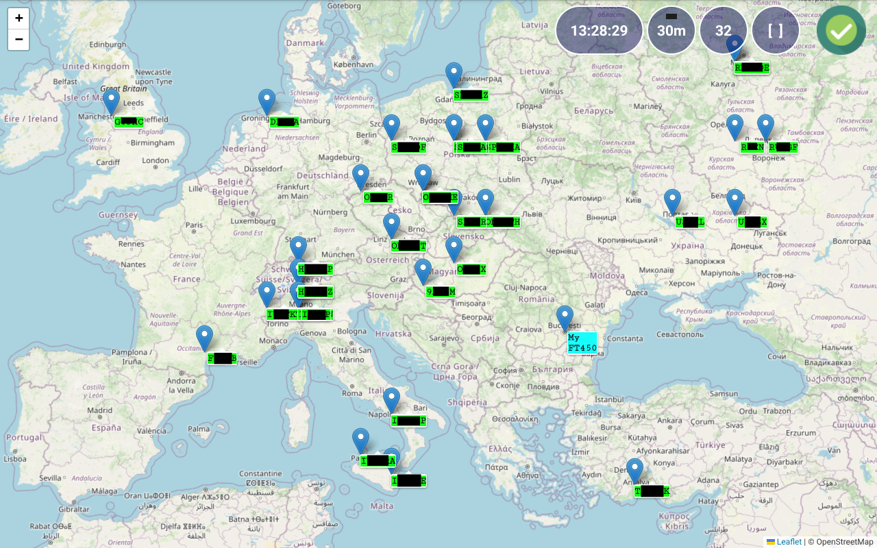
Enter the TCP port to be used for the server and server password. Local IP address is automatically filled, and you must use it to configure the client Pocket RxTx4. Tap on MANUAL button to toggle between MANUAL and AUTO start modes. When AUTO is selected, server will start when you start the application. Tap OK button when ready. The form will be closed. Now you can start the server by tapping on SERVER button. If you want to edit server configuration later, long press on the SERVER button.
When server mode is active, in the radio panel a green icon will be shown.
![]()
When a client is connected to the server, a green ring will be shown around the tuning knob.

Orange SERVER button when?
Audio loopback
Use this button to activate/deactivate Audio Loopback mode. When USB or Bluetooth connection mode is selected, Audio Loopback creates a local audio loop. If pRxTxSrv connection mode is selected, Audio Loopback works over the network, through the pRxTxServer4 running on a PC/Mac at the other end. This feature is useful to test that audio channel is working as expected for both Rx and Tx, without the need to connect to a radio. It works similarly with the Echo mode in Echolink. A local (or over the network) audio loop is created. Go to the main radio page by pressing on START button and then long press on ON/OFF button.
A-LOOP will be shown in the frequency area.

After pressing on PTT, your voice will be recorded, and PTT button background will change to orange. Recordig is sved locally (when in Bluetooth or ISB mode) or remotely (when pRxTxSrv4 mode selected). When you release PTT, the voice will be played back so you can check that your Headset or Mic/Speaker are working as expected.
When pRxTxSrv connection selected, you verify the full audio path (Android Device -> pRxTxServer4 ->Android Device, so you can check the network link quality too.
Scripts
You can define scripts in the server app as explained here. These scripts can then be executed by assigning them to new commands in Pocket RxTx. This can be done by tapping SCRIPTS button in the RADIO menu. You will get this page.
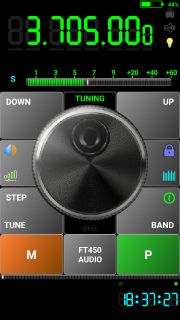
To define a new script, tap on one of the 16 orange buttons.
You will be prompted to enter an alias for the script (max. 7 characters to prevent wrapping).

Enter the same alias (case sensitive) as the one defined in the server application (NOTEPAD in the server scripts example) and then tap OK. You will be notified that the script alias was saved and then returned to the RADIO menu page.
![]()
You can now assign the script execution to one of the users defined blue buttons. Long press on the blue button you want to use (let’s say second one) and select from the panel the newly added command (in orange).
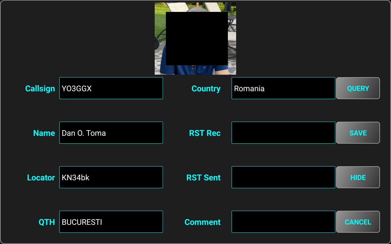
Script alias will be displayed on that button. When connected to the radio though the pRxTxServer4 application, if you tap on the newly defined button, the associated script will be executed on the server. If the script returns a text, it will be displayed as a pop-up in the Android app.
FT8 decoding (PRO only)
The application can decode FT8 transmissions when connected to a WebSDR server, or when connected to your own radio over USB or over the network (through pRxTxServer4). To use this feature, you must be connected to the Internet, as the clock used for decoding is based on the NTP servers’ data.
NOTE: You can use this feature (to display and filter previously received FT8 data) even if not connected to the radio.
FT8 decoder activation
To use this feature, you must assign it to one of the 5 user defined blue buttons. As an example, let’s long press a user defined button.
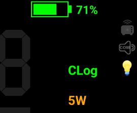
Another way to access it is by long pressing on the green SET/P button and then selecting FT8 DECODER. Tap FT8 Decoder button. The user defined button name will be changed accordingly.
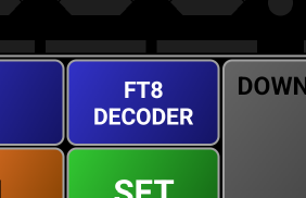
Now connect to the WebSDR server or to your radio over network or USB.
![]()
When you tap on the FT8 Decoder button, the tuning knob panel will be replaced by the FT8 panel, frequency display will be moved to the status bar and replaced by a black panel where the FT8 transmissions frequency slots will be displayed. The frequency will be automatically set to the FT8 frequency for the current band.
The FT8 panel contains the following elements:
[1] – Frequency slots for each FT8 transmission will be displayed here. Each transmission is 50Hz width and the vertical size is proportional with the received signal SNR. Frequency slots from the current cycle are represented in light green. When a new slots set is displayed, the old one is not cleared but dimmed each time with 50%. In this way you can better detect potential free spaces to be used for transmission (when this feature will be available).
[2] – The header of the table where the FT8 transmissions info is displayed.
[3] – Info about each FT8 transmission will fill one line from this table.
[4] – A virtual LED showing current decoder status. When a ~13s FT8 chunk is received, the color will change to green and will remain dark during the interval between FT8 transmissions (~12s).
[5] – Button used to select the FT8 band. When you tap it, only the bands available on the selected WebSDR server or radio will be displayed (from 160m to 23cm).

Currently selected band button is displayed in green. For each band, corresponding frequency is shown below the band name. When you tap on another band button, the WebSDR or radio frequency and mode will be automatically changed.
[6] – Tap on this button to show the stations transmitting in FT8 on a map. More details on how to use the map feature are available here.
[7] – Tap here to filter the data in the table. More details about the filtering feature are available here.
[8] – Tap this button to clear current data from the table. The data is not removed from the device. Long press on this button to remove the data from the device. More details about FT8 data are stored and are available here.
Receiving FT8 data
When the FT8 panel is active (visible), data starts to be decoded as soon as each ~13s chunk is received and displayed in the table. For each transmission, the following information is available and visible by default in the table:
- TIME - start transmission timestamp.
- SNR - signal to noise radio (in dB) for the received transmission.
- CALLED – the callsign of the called station (or CQ if a CQ call).
- CALLER – the callsign of the calling station
- DATA – based on the call status, can be a SNR report, a locator, RRR, 73 or RR73.
- DIST – if data contain a locator and a caller callsign, distance between that station and the current receiver is automatically calculated and added to the table.
The following information is available too, but visible only if you scroll horizontally, by dragging the table to the left:
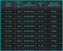
- FREQ – Rx tuned frequency in MHz for the FT8 reception. This is the standard frequency for the current band, not the exact frequency of the slot.
- FOFFSET – the frequency slot frequency in the current audio channel (300-2700Hz).
- DATE – date of the call, to be used later for filtering or logging.
- DRIFT – transmission time drift (in seconds) from the standard UTC time.
- RECEIVER – can be the callsign of the WebSDR server or your own radio model, depending on what you are using for reception. Can be used for further filtering.
Storing FT8 received data
All FT8 received data is stored in a local csv (comma separated values) file named ft8.csv. The file is stored internally but can be exported or imported through the FILE IMPORT/EXPORT functions described here. By default, in the table or map you will see only data received in the current day, currently selected band and receiver. To see data for another band, day or receiver, use the filtering function, as described here.
Filtering received FT8 data
You can filter the data in the table by tapping on a value and pressing FILTER button. When you tap on a value, the color of the cell will be changed.
![]()
Let’s say we want to filter the table for the stations calling CQ. Tap CQ anywhere on the table and then on FILTER.
Now only the stations calling CQ will be shown on the table.

Only the following columns are currently available for filtering:
· CALLED (callsign or CQ)
· CALLER (callsign)
· FREQ
· DATE
· RECEIVER
By default, only data for the current frequency, date or receiver is displayed in the table. Any new filter is applied to the existing data in the table.
NOTE: In the current version, you cannot filter using more than one value for a column. When you search for a callsign, all lines containing that callsign in both CALLER and CALLED fields are matched.
If you tap on a callsign in CALLED or CALLER columns, that callsign will be used for filtering, no matter if it is present in CALLED or CALLER column. If you tap on the CALLED or CALLER column title (in table header), you can select from all available callsigns in the table. If there are more than 40 lines in the table containing that callsign, you will be asked to enter first char(s) of the callsign you want to search for.
To select FREQ, DATE or RECEIVER, you can tap anywhere on the column, including on the column header. In this case, the selected column header text will switch colors between cell background and text. If you click on another cell from the same column, that cell will change color.


After you select a cell or column header, tap on FILTER button. If you select for filtering a frequency, date, or receiver, you will be prompted with a selection panel. You have the option to select a specific value, or ALL, if you want all possible values for that field to be matched.
For example, if RECEIVER was selected, you can choose between the data from the WebSDR server with the callsign YO3GGX or for the data received using the Yaesu FT450 transceiver.

Remember that by default, if no filtering applied, only the data from current date, frequency and receiver is displayed, in both table and map.
Using the map
When some data is already available in the table, you can tap on MAP button to display all received stations callsign on a world map.

Receiving station (My FT450 in this example) is displayed with a different background color (cyan), the transmitting stations are all displayed in green. Because FT8 locators are transmitted using only 4 chars, precision is not so good, the grid being ~ 100km x 50km. The pinpoint shows the center of this big grid (‘MM’ added to the 4 chars locator).
You can use pinch and zoom and tap and drag gestures to get more details over a specific area of the map.
If you tap on a station callsign and your QRZ.com account was previously connected as described here, a textbox will be displayed with more info about the station.
If the first 4 chars of the locator received in the FT8 call are the same as the first 4 chars of the locator registered for the callsign in QRZ.com, the more precise locator will be used, and the station pinpoint position will be updated on the map.
|
Before tapping on station callsign (approximate location – 4 chars locator) |
After tapping on station callsign (more precise location – 6 chars locator) |
|
|
|

In the top right side of the map, you can see 5 labels/buttons.
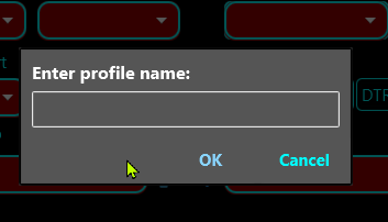
1 – UTC clock, updated in real time, but currently using device clock, not Internet Time.
2 – Currently selected band. On this label/button a virtual LED goes green during the timeslot when data is received. You can tap it on to select another band. It has the same functionality as the BAND button from the FT8 panel.
3 – Number of stations currently displayed on the map. You can tap on it to temporarily clear the map, or long press it to clear the whole ft8 data stored on the device (local ft8.csv file is removed). It has the same functionality as the CLEAR button on the FT8 table.
4 – You can automatically set the zoom to fit all stations by pressing this label/button. Any station details box is removed from the map.
Exiting FT8 mode
To exit FT8 Decoding mode end return to the standard radio panel, tap again on the FT8 DECODER button.
Using the application on devices with a small screen (ex. Network Radios)
When an Android device has a screen size below 4.5”, COMPACT mode is automatically selected. In this case, some of the GUI elements are missing, so operation is different for some of the application features. You can still disable COMPACT mode from the SYSTEM menu, as described here, but the screen will become in most situations unusable, especially if the resolution is below 800x480 pixels.
This is how the screen looks on a device in COMPACT mode.
|
|
|
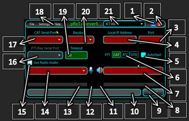
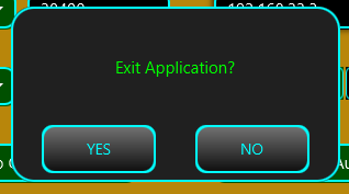
Call logging
You have the possibility to log calls directly onto your device.
NOTE: This feature is available in the free version of the application only in the WebSDR client mode.
An automatic query using QRZ.com is performed when entering a callsign in a log entry. An XML QRZ subscription is recommended for full functionality. A free subscription may not provide all the information required to fill in a call log record. To configure your QRZ.com connection, follow the steps described here.
Call log format
The call log is stored in the application as a standard ADIF file. You can have maximum one local log file at any moment. Multiple files are not supported. The standard format for the call log file name is the following:
logbookyyyyMMddhhmmss.adi where:
yyyy – year
MM – month (01-12)
dd – day (01-31)
hh – hour (in 24h format)
mm – minute (0-60)
ss – second (0-60)
when the call log file was created (UTC time).
This is how the header of the ADIF file will look:
#
# Pocket RxTx logbook, © 2018-2025 by Dan Toma (YO3GGX)
# https://www.yo3ggx.ro
#
# Created: 12 03/12/2025 10:12:05 (UTC)
<ADIF_VERS:5>3.0.8
<PROGRAMID:11>Pocket RxTx
<PROGRAMVERSION:13>Version 2.1.0
<EOH>
The created ADIF file is based on the specifications for version 3.0.8 from here:
http://www.adif.org/308/ADIF_308.htm
Only the following fields are added to the log if available (from QRZ database or from a local entry in the call log form):
ADDRESS - contacted station's complete mailing address
AGE - contacted station's operator's age in years in the range 0 to 120 (inclusive)
BAND - QSO Band
CALL - contacted station's Callsign
COMMENT - comment field for QSO
COUNTRY - contacted station's DXCC entity name
CQZ - contacted station's CQ Zone in the range 1 to 40 (inclusive)
DISTANCE - the distance between the logging station and the contacted station in kilometers. This is calculated in the application based on latitude and longitude (if available) or on maidenhead grid squares.
DXCC - contacted station's DXCC Entity Code
EMAIL - contacted station's email address
FREQ - QSO frequency in Megahertz
GRIDSQUARE - contacted station's 2-character, 4-character, 6-character, or 8-character Maidenhead Grid Square
IOTA - contacted station's IOTA designator
ITUZ - contacted station's ITU zone in the range 1 to 90 (inclusive)
LAT - contacted station's latitude
LON - contacted station's longitude
MODE – QSO Mode
MY_CITY – my station’s city
MY_COUNTRY – my station's DXCC entity name
MY_CQ_ZONE – my station's CQ Zone in the range 1 to 40 (inclusive)
MY_DXCC – my station's DXCC Entity Code
MY_GRIDSQUARE – my station's 2-character, 4-character, 6-character, or 8-character Maidenhead Grid Square
MY_IOTA – my station's IOTA designator
MY_ITU_ZONE - my station's ITU zone in the range 1 to 90 (inclusive)
MY_LAT – my station's latitude
MY_LON – my station's longitude
MY_NAME – my name
MY_POSTAL_CODE – my station's postal code
NAME - contacted station's operator's name
QTH - contacted station's city
TIME_OFF - HHMM or HHMMSS in UTC
TIME_ON - HHMM or HHMMSS in UTC
TX_PWR – my station's power in Watts
WEB - contacted station's URL
To build all ADIF record fields, the following data is extracted from the QRZ database, for both my station and for the contacted station (as described in https://www.qrz.com/XML/current_spec.html):
call - callsign
dxcc - DXCC entity ID (country code) for the callsign
fname - first name
name - last name
addr1 - address line 1 (i.e. house # and street)
addr2 - address line 2 (i.e, city name)
zip - Zip/postal code
country - country name for the QSL mailing address
lat - lattitude of address (signed decimal) S < 0 > N
lon - longitude of address (signed decimal) W < 0 > E
grid - grid locator
email - email address
url - web page address
image - full URL of the callsign's primary image, used just to display the picture in the Pocket RxTx GUI, not stored
cqzone - CQ Zone identifier
ituzone - ITU Zone identifier
born - operator's year of birth
iota - IOTA Designator (blank if unknown)
Adding a call log entry
When connected to a radio (or a WebSDR server), tap the UTC clock area to start logging for the current call. An empty call record form will be displayed.
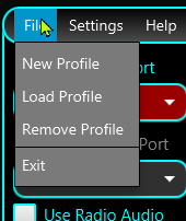
Enter the callsign of your correspondent in the Callsign textbox. If you configured QRZ.com connection, tap on QUERY button.
All the form fields will be filled in with the info gathered from QRZ.com, except the RST Rec/Sent values.
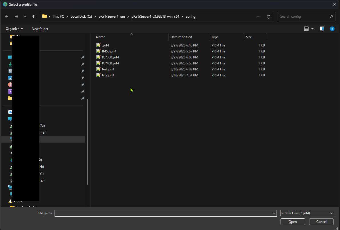
If you tap on the correspondent picture, this will be shown on the full screen. Tap again to return to the call log form.
Fill the info about RST Rec/Sent and a comment (this is not mandatory) and tap SAVE button. The information for the current call will be appended to the existing log file. If no local call log file is available, a new one will be automatically created, in ADIF format, with standard header information. A short message will be displayed showing that the info was saved. The end call time is set now. Time used is UTC time. The following information is stored in the ADIF file for each record:
Returning to the call before saving call info
You can return to the current call without losing the form information by tapping on HIDE button. A green CLog symbol will be shown in the frequency display area, to know that current call record is still open.
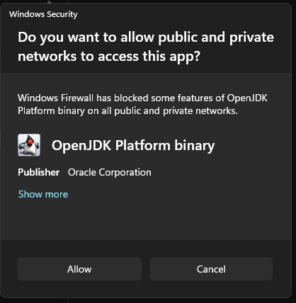
You can return to the call log form by tapping UTC clock area again.
Discarding current call record
You can discard current call record by tapping on CANCEL button in the call log form. The form will be closed, returning to the radio panel. CLog symbol will disappear.
Sending Call Log file by email
You can send the local Call Log file by email following the procedure described here.
Removing local Call Log file
To remove existing local Call Log file, follow the procedure described here.
Using external third-party devices with Pocket RxTx
The application provides support (including PTT) for the following hardware audio devices:
BlueParrot B450XT Bluetooth headset
Inrico/Anysecu B01 Bluetooth speaker/microphone
ABBREE Bluetooth Handheld Speaker Mic
Mini Bluetooth Remote Photo Shutter
Click on the links for more details about each device. More devices using similar protocols may work with the application, but only the ones below were tested by myself as I own them.
BlueParrot B450XT (PRO only)
This is a high-quality mono Bluetooth headset with PTT button.
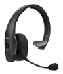
To use it with Pocket RxTx, you must pair it with your Android device first, as explained in the device documentation. After you start pocket RxTx, select it as both Headset Audio In and Audio Out device (SCO mode). Audio device icon will change to the BlueParrot image. Long press on the BlueParrot image to start searching for BLE devices. You will be asked for precise location rights. This is a Google requirement for Bluetooth discovery to work.

Tap on B450-XT v1.12. You will be notified that PTT button was assigned. From now on you can use the PTT button from the headset as application PTT. To check that it is working, tap the headset PTT button. The headset battery level area background will go red, to show you that the event was assigned correctly.
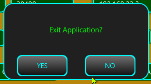
No need to assign the button for PTT through the application menu, this is done automatically.
I recommend you to test audio using the Audio Loopback feature, as described here.
Anysecu B01 (PRO only)
This is a very popular Bluetooth Speaker/Mic with a PTT button, a clone of Inrico B01.
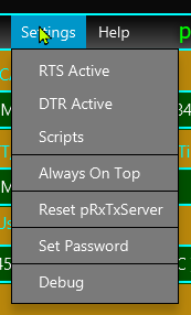
To use it with Pocket RxTx, you must pair it with your Android device first, as explained in the device documentation and then select it as Headset Audio In and Audio Out device (SCO).
Power on the mic and long press on the audio icon to start searching for BLE devices.

Select B01_BLE from the list. A pop-up message will confirm that the PTT button was enabled. Cycle power the mike. You will be notified when connected. Test functionality by pressing the PTT button on the mike. The background of the battery level will go red when the PTT button is pressed.

No need to assign the button for PTT through the application menu.
ABBREE Bluetooth Handheld Speaker Mic
This is a popular and cheap Bluetooth speaker/microphone with PTT, available on AliExpress.
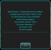
You must first pair it with your Android device and select it as Headset Audio In and Out for the application. This device is usually shown as KST_vHMIC007. Power it on. This device PTT button is shown as a media button. Go to MENU > RADIO > PTTKEY > DOWN/UP (learn). Press and keep pressing the PTT button.
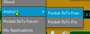
Tap SET to save media keycode 90 for PTT Down. You will be prompted to set the key for PTT Up. Release the PTT key.

Tap SET to save the keycode 89 as PTT up. You can now check if it is working as expected from the startup page. When you press the key, the background of the label reserved for the headset/mike battery level goes red.
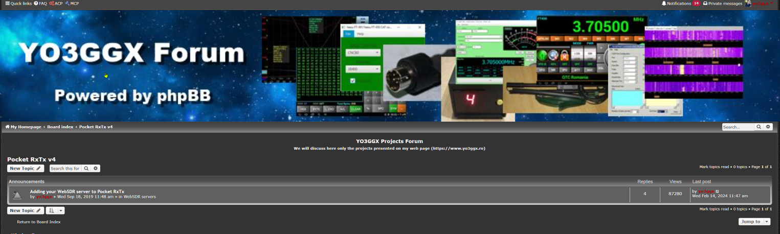
When you release it, it goes back to green.
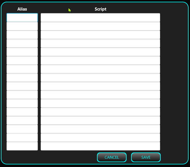
BLE PTT Button
This is another popular Bluetooth BLE PTT button, available under different brands.

This button appears in the Android Bluetooth settings when scanning for Bluetooth devices but cannot be paired from there. Usually the name is ELET-PTTxxxxxx where xxxxxx is a 5 characters hex number. Thio device must be learned by the application. Press the button to activate it. The blue LED will start blinking. In the startup page, long press on the audio icon to start Bluetooth BLE discovery.
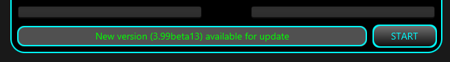
Tap on ELET-PTT… You will be asked to shortly press the button. If successfully detected, you will receive confirmation. If not, retry the process from BLE discovery. You can now check if it is working as expected from the startup page. When you press the key, the background of the label reserved for the headset/mike battery level goes red.
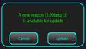
When you release it, it goes back to green.

Mini Bluetooth Remote Photo Shutter
This is a very cheap BLE shutter button available on AliExpress.
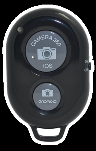
This is a BLE button that is seen by the system as a HID device (keyboard). From Android Bluetooth settings, pair this device, usually shown as AB Shutter3. Then go to MENU > RADIO > PTTKEY > HW KEY DOWN/UP (learn). Press the key you want to be used as PTT and keep it pressed (let’s say the big button).
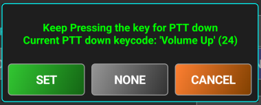
The key has the same code as Volume Up, so device volume will no longer be possible to adjust, as this will be used as PTT. Tap on SET to save the code for PTT down.
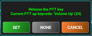
Release the key when you are prompted to press the key for PTT down. You will see the same code. In this case, a single keycode is used for both PTT Down and PTT Up, with two different actions (PRESS/RELEASE). Tap again SET to save it.
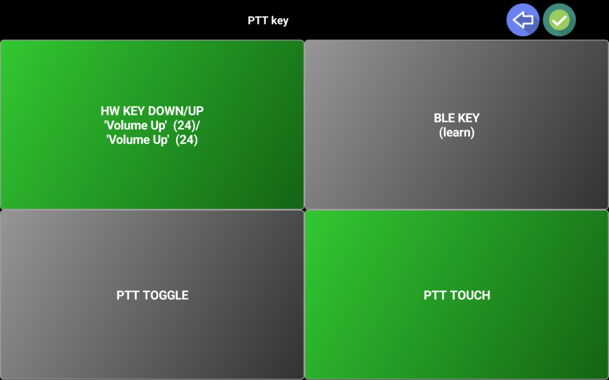
PTT key definition will be shown on the button and background will go green. You can now check if it is working as expected from the startup page. When you press the key, the background of the label reserved for the headset/mike battery level goes red.
When you release it, it goes back to green.

Application shortcuts
Below is a table containing all available application shortcuts, that can speed up some operations or provide some hidden features.
|
Shortcut |
Function |
|
Long press on app title in the startup page |
Manually enter your own locator (not necessarily if Location Services is activated). If Location Services is activated, own locator is automatically updated. If you change your location, the locator is not updated, even if Location Services is activated. To force auto-update the location, enter the value “no”. You are prompted to enter grid locator using 4,6,8 or 10 chars, following the standard. |
|
Long press on the radio brand/model button in the startup page |
Re-download radio configuration file from the central repository. Info box is updated too. |
|
Tap on the radio image in the startup page |
Display radio protocol document |
|
Long press on the radio image in the startup page |
Display radio user guide |
|
Long press WFZOOM button |
Reset zoom to 1x |
|
Tap waterfall with 3 fingers |
Reset zoom to 1x |
|
Long press audio icon in RADIO mode |
Activate BLE KEY learn process. |
|
|
|
Server application (pRxTxServer4)
This is a portable java application that can be run on any system running Windows, MacOS or Linux (Intel/Arm), including a Raspberry Pi. This will connect to your radio over a USB/Serial/Audio cable and work as a radio server for Pocket RxTx4.
This allows you to operate your radio even if you are not at home, connected over WiFi or 4G/5G.
You can run multiple instances of the server application, but you need to create a dedicated folder for each instance. In this mode, you can control multiple radios, by running each server instance on a different TCP port. You can then create one profile for each radio in Pocket RxTx and connect to one of the server instances, without the need to do something on server side.
NOTE: The CAT engine, used to control the radio, including the parameters update loop runs on this server, not on the client, so all CAT traffic is local. Only parameter changes are transmitted to the client. CAT commands, control signals and audio are all transmitted over a single TCP socket.
You can use Pocket RxTx as a server application too. See here for more details.
Server application has 2 variants: FULL (using a graphical interface) and MINI (console only, to be run mainly on small systems without a graphical interface).
NOTE: Always use the exact same version for the Pocket RxTx and psrv4 applications.
Downloading server application
The application is distributed as a portable package (required Java runtime included in the package) or as a jar file.
A download web page is available at the following url:
https://prxtx.yo3ggx.ro/4/download.html
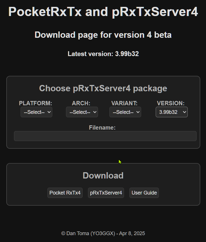
You can select your platform, architecture, variant and version, according to the combinations from the table below.
|
Platform |
Architecture |
Variant |
Version |
|
|
|
|
|
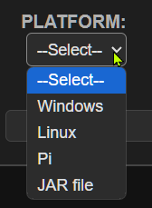
“Linux” is used for Intel based Linux systems and “Pi” for Arm based Linux systems. Pi platform can be RaspberryPi, OrangePi or any other Arm based platform.
NOTE: Currently, packages for the following combinations (less likely to occur) are not available:
· Linux/32bit/FULL
· Pi/32bit/FULL
For these platforms you can still run the FULL variant using the JAR file, as described here.
Download the zip file to a dedicated local folder on your computer, named (let’s say) psrv4.
On Linux computers unpack the archive using the command:
unzip package_name.zip
On Windows computers, right click on the zip file and select Extract All. Select the newly created folder as destination.
Running packaged server application
Depending on the platform/variant you will see some scripts used to start the application, as in the following table.
Attention!!! On Linux/Pi, before running the application, from the application folder, run the following commands:
sudo chmod +x *.sh
sudo chmod +x bin/java
sudo usermod -aG audio $USER
Normal start:
|
Linux |
Windows |
||
|
MINI |
FULL |
MINI |
FULL |
|
psrv4mini.sh |
psrv4full.sh |
psrv4mini.bat |
psrv4full.bat |
Start with debug console (different than activating debug in the app menu):
|
Linux |
Windows |
||
|
MINI |
FULL |
MINI |
FULL |
|
psrv4mini_debug.sh |
psrv4full_debug.sh |
psrv4mini_debug.bat |
psrv4full_debug.bat |
NOTE: On some Windows systems you may need to unblock the startup scripts. Before running the start script, right click on it and select Properties.
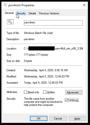
If you see the message “This file came from another computer …” check Unlock and click Apply, then OK.
Now you can start the app by double-clicking on the bat script.
Running the app using the JAR file
Use the jar file if you have a Linux platform/architecture/variant for which there is no package available. Download the zip file as described here.
If you want to run the FULL variant of the server application, you will need openjdk, openjfx and JavaFX jmods.
Operating the Full variant – GUI based (psrv4full)
The look and feel of the server application does not depend on the OS. Each packaged version provide a script to start the application in release mode or with a debug console, as described here.
NOTE: The Windows/x86_64 package can be run on an arm64 Window computer too, in x64 emulation mode, transparent for the user. Currently there is no native arm64 package available. As the load on the system is very low, emulation performance is excellent on all modern arm64 Windows computers.
On Linux computers, you may need to make the scripts executable after extracting the files from the package archive.
Use the following command, in the folder where you extracted the files
sudo chmod +x *.sh
Run the corresponding script for the platform to start the application.
Creating an application profile
As soon as you start the application for the first time, you will be prompted to create the first profile.

An application profile contains all the settings required to run the server. You can define an unlimited number of profiles, for example one for each of your radios. You can then switch configuration by just selecting another profile, without the need to enter all data again. Enter the profile name. My suggestion is to use radio model, let’s say FT450. You can use both upper and lower case. Click OK when ready. The main application panel will be displayed.
The main panel
This is how the main panel will look at first start or after a new profile was created.
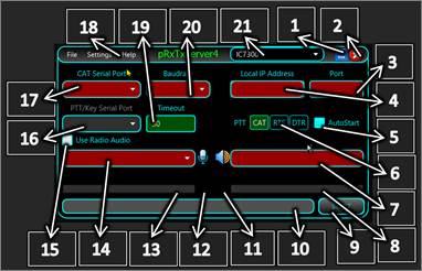
All fields that must be set are displayed in red.
[1] – Click to minimize pRxTxServer4 Window.
[2] – Click to close the application. You will be prompted to confirm.

[3] – Entre the TCP port for the server to listen to. Use any free port between 1025 and 65535.
[4] – Here you will find local IP Address. This is a combo box, so if the computer has multiple IP addresses, all of them will be on the list. This field is just for information purpose. The application will always listen on all available IP addresses (0.0.0.0).
[5] – Check this box to automatically start listening when you run the application.
[6] – You can set PTT over CAT, or over the RTS or DTR lines from a serial port. Take care that some transceivers may select TX audio from front Mic connector or from back DATA/USB port, depending on how you set PTT. Usually PTT over the DATA port (RTS or DTR) is used to force back connector audio.
[7] – You must select here the audio device assigned to the Radio for Rx.
[8] – Here is a bargraph showing the audio level coming from the radio (Rx).
[9] – Click here, after you configure all fields, when START is displayed, to start the server (start listening). When in listening mode, the button shows “STOP”. Click on it to stop listening.
[10] – This is a status bar where you can see different information during the operation.
[11] – This “RX” symbol will flash when data from the radio is received over CAT.
[12] – This “TX” symbol will flash when data is transmitted to the radio over CAT.
[13] – Here is a bargraph showing the audio level coming from the client micrphone (for Tx).
[14] – You must select here the audio device assigned to the Radio for Tx.
[15] – Check this box to use audio to/from the radio.
[16] – Select the serial port to be used for PTT. If [6] is set to PTT over CAT, this field must be left empty. PTT serial port can be the same as the one used for CAT or a different one, depending on your specific CAT interface).
[17] – Select the serial port to be used for CAT.
[18] – Application menu. Check here for more details.
[19] – You can set a PTT timeout (in seconds). If PTT is activated, it will be automatically released after this interval. Keep it 0 for no PTT timeout. This works only in PRO version.
[20] – Select the Baud Rate for the serial communication with the radio. Check this value to be the same as the one set in the radio CAT menu.
[21] – Here you can see the name of the currently selected application profile. Click to directly select another profile, if more than one defined.
Application menu
The application menu has 3 submenus: File, Settings and Help.
File menu
Use this menu to create a new application profile or to remove an existing one.

Available actions:
· NewProfile - Use the same procedure as when you create the first profile when the application is started for the first time and described here.
· Load Profile - As profiles are not automatically removed in any situation, after application full reset (as described here), you can reload them by clicking on Load Profile. A dialog box will be displayed, letting you select the profile you want to load.

Select it and then click on Open. If you run the application for the first time, you will be asked to allow access to the network for the application. Click Allow.

All data from the selected profile will be loaded in the application.
· Remove profile - To remove an existing profile, select it from the top combo box and then click File > Remove Profile. A pop-up window will confirm the operation. Associated *.prf4 file is not automatically removed, if you want to save it for future use.
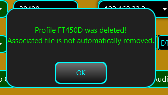
If a single profile exists, this cannot be removed. If you try to do it, a pop-up will be displayed.
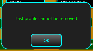
Exit – click here to exit the application. You will be asked to confirm.

Settings menu
You can set more parameters by accessing this submenu.

Available settings:
· RTS Active – If checked, RTS line on the selected CAT serial port will be forced to active, otherwise will be inactive. Some radios CAT interfaces (like Kenwood TS590SG) require this line to be kept active.
· DTR Active – If checked, DTR line on the selected CAT serial port will be forced to active, otherwise will be inactive.
· Scripts – used to define scripts than can be triggered by the client. See here how to configure scripts on the client and here on the server.
· Always On Top – If checked, the application will be displayed on top of the other applications.
· Reset pRxTxServer – Click here to restore the application to factory default. Application configuration file is removed. Profile files are kept. As soon as you confirm, you go back to the first step where you are asked to create the first application profile, as described here.
· Set Password – Click here to set the password for the client authentication over the network. Password is transmitted in encrypted format (RSA with asymmetric keys) over the network. You must set the same password at both ends.
Help menu
Use this menu to get more information about this app and my other hardware and software projects, or to update the application.
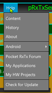
Available options:
Content – Access a web page containing this document, including a clickable table of content. The page uses a Google Translate script that allows you to select the language of the displayed document.
History – Display a table containing all changes done in the app, with time stamps, details, etc. This page is updated in real time. You can see below just an extract from this table.
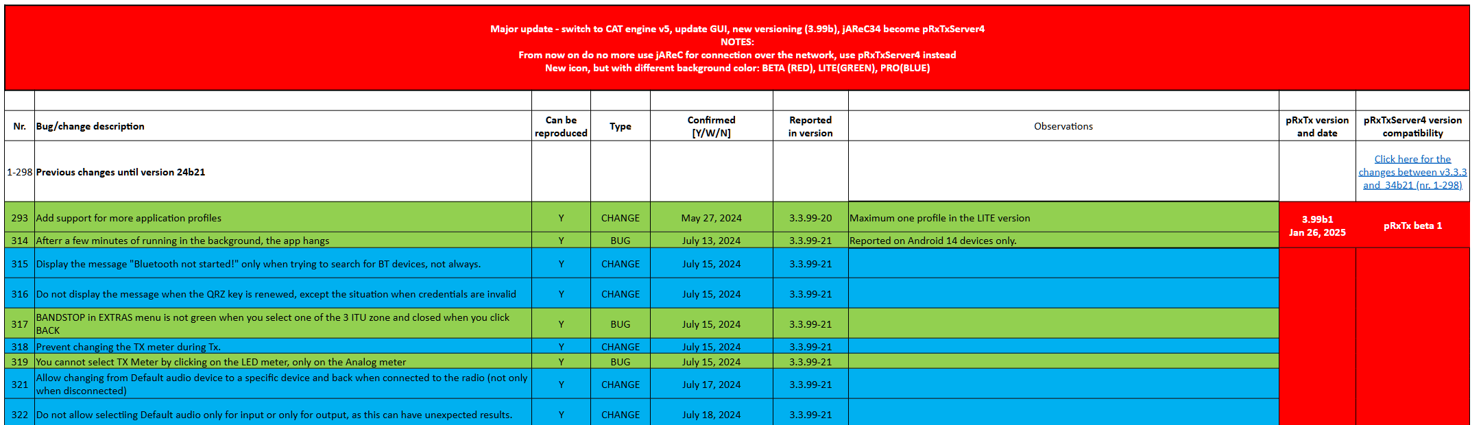
About – Get more details about the current version you are running, like Compile time, OS/app/Java version and system architecture.
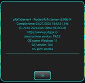
Android – Contains links to Google Play Store, from where you can download and install the client Android application (Pocket RxTx), bot LITE and PRO versions.
![]()
For each version, a QR code is displayed for easier access from a Smartphone and links to the online or offline documentation.

PocketRxTx Forum – direct access to the forum dedicated to both client and server Pocket RxTx applications.

Check for Update – More about how application Auto Update works here.
My Applications – Direct link to my other applications available for download.
My HW Projects – Direct link to my hardware projects, with full documentation.
NOTE: The application includes a safe feature, but only in the PRO version. If the client is disconnected unexpectedly, the radio will automatically power off, but only if RADIO OFF is activated in the client RADIO menu.
Defining scripts
This feature is only available in the PRO version of the client, so there is no reason to define scripts on the server if you use the LITE version. Sometimes you want to control external devices connected to the server, from the client. This can include antenna switches, power amplifiers, PSUs, etc. For this you can define scripts for each specific operation (ON/OFF, select a parameter, etc.). Scripts can be used on all platforms supported by the server app (Windows, Linux, Raspberry Pi, Mac). To define a script, click on Scripts in the Settings menu. A configuration page will be displayed.

You can define up to 16 scripts. For each script, enter an alias (max. 7 chars) and the full path to the script. Just as an example, on a Windows platform, let’s define a script that will launch Notepad. As soon as a script is defined, in the right part of the window a RUN button will appear.
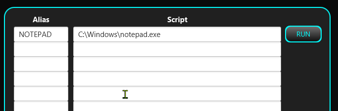
You can check that the script was correctly defined by running it. Click on RUN. Notepad will be displayed. The script can contain an unlimited number of parameters and can return a text. That text, if available, will be displayed as a pup-up in the client after the script is executed.
After you check that the script works as expected, click on SAVE. Script information will be saved in the profile. You can fill in the lines in any order. To remove a script definition. Clear the line and click on SAVE.
Application update
If a new version of the application is available, when you start the application, you will be notified about that in the application status bar.
![]()
You can directly click on the status bar to start the update process. You must confirm by clicking on Update button.
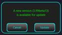
Update process is very fast, takes only a few seconds and keeps application configuration and defined profiles unchanged. You will then be notified that you must restart the application to run the new version.FT450NET
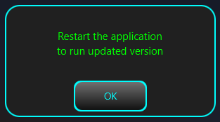
Click on OK button.
NOTE: To be notified about the available updates, you must run the application using the standard script, not the debug one.
If you want to update the application later, you can access the update process from the HELP > Check for Update menu item.
Operating the MINI variant – Console based (psrvmini4)
This is a stripped-down version of the GUI desktop application that can be run especially on very small systems running Linux and without a desktop environment. Offer all the functionality available in the GUI application with simple command line scripts and switches. Console application does not use profiles, but you can run as many instances as you want, if stored in separate folders. To download MINI version, follow the procedure described here by selecting MINI variant.
NOTE: On Linux platforms, you must make the script and java executable by running the command:
sudo chmod +s *.sh bin/java
To start the application, run the script (psrvmini.sh for Linux or psrv4mini.bat for Windows). A list of available switches will be displayed.
-------------------------------------------------------------
pRxTxServer4 v3.99b32 console edition (MINI)
(C) 2014-2025 Dan Toma (YO3GGX)
https://www.yo3ggx.ro
Java runtime version: 21.0.6
Compile time: 04/08/2025 20:42:42
OS name: Linux
OS version: 6.11.0-21-generic
OS arch: amd64
-------------------------------------------------------------
Usage:
-h Display this info (default if no switch used).
-l List all available parameters with current values.
-n Update to the latest available version.
-x Start the server.
-b <BaudRate> BaudRate can be 4800, 9600,19200,38400,115200 or
any other standard value between 110 and 921600
-c <CAT serial port> Set serial port to be used for CAT using the name,
as displayed using '-l' parameter
-y <PTT serial port> Set serial port to be used for PTTT using the name,
as displayed using '-l' parameter,
only if PTT is not over CAT (see '-m').
-m <PTT mode> PTT mode, can be CAT, RTS or DTR (case sensitive).
Default value is CAT.
-u <PTT Timeout> PTT Timeout (in seconds). Use 0 for no PTT timeout.
Defaults value is 0. Does not work in LITE version.
-r <ON/OFF> Activate(ON)/Deactivate(OFF) RTS line for the CAT
serial port. Default value is OFF.
-d <ON/OFF> Activate(ON)/Deactivate(OFF) DTR line for the CAT
serial port. Default value is OFF.
-g <ON/OFF> Activate(ON)/Deactivate(OFF) debug mode.
-i <audio in DevID> Set audio in device ID, as displayed using '-l' parameter.
serial ports and audio devices.
-o <audio out DevID> Set audio out device ID, as displayed using '-l'
parameter.
-t <tcp port> Set TCP port to listen on. Without parameter display.
-p <password> Set password to <password>.
-s <alias>=<scriptname> Script alias and scriptname (must contain the full path).
-------------------------------------------------------------
This is the latest version available.
Available command line switches are self-explanatory.
NOTE: If you use one of the switches without a parameter associated (-h, -l, -n, -x), only one is accepted. If you use more than one, only the first one is executed.
First step is to list the available interfaces (serial and audio), using the switch -l. This is a sample result on a Linux computer where a Yaesu SCU-17 CAT audio interface is connected.
Audio In devices:
(4) - alsa_playback.java [default]
(8) - CODEC [plughw:1,0]
(9) - PCH [plughw:2,0]
(10) - Webcam [plughw:3,0]
Audio Out devices:
(4) - alsa_playback.java [default]
(5) - HDMI [plughw:0,3]
(6) - HDMI [plughw:0,7]
(7) - HDMI [plughw:0,8]
(8) - CODEC [plughw:1,0]
(9) - PCH [plughw:2,0]
Available serial ports:
/dev/ttyUSB0
/dev/ttyUSB1
Audio in device: Not selected
Audio out device: Not selected
Listening TCP port: not set
Password: Not set
BaudRate: not set
CAT serial port: Not selected
PTT Mode: CAT
PTT Timeout: 30s
RTS line: deactivated
DTR line: deactivated
Debug: deactivated
NOTE: If you run MINI variant on a Linux system with a graphical interface and you are connected over SSH, check that pulseaudio is not installed, as this may require access to the Xserver and then the application will not work.
You can now configure all the parameters one by one, or all in a single line. Let’s configure the app to use the Yaesu SCU 17 interface. I want to set the parameters as follows:
Audio In device: (8) - CODEC [plughw:1,0]
Audio Out device: (8) - CODEC [plughw:1,0]
CAT serial port: /dev/ttyUSB0
PTT serial port: /dev/ttyUSB1
PTT mode: RTS
PTT timeout: 0 (no timeout)
Listening TCP port: 7264
Password: mypass
BaudRate: 38400
RTS line: deactivated (default value, no need to set)
DTR line: deactivated (default value, no need to set)
Debug: deactivated (default value, no need to set)
I’m using the following command:
./psrv4mini.sh -i 8 -o 8 -c /dev/ttyUSB0 -y /dev/ttyUSB1 -m RTS -u 0
-t 7264 -p mypass -b 38400
The result will be:
Selected audio in device: CODEC [plughw:1,0]
Selected audio out device: CODEC [plughw:1,0]
CAT serial port: /dev/ttyUSB0
PTT serial port: /dev/ttyUSB1
PTT mode: RTS
PTT timeout: 0s
TCP port: 7264
Password: <saved>
BaudRate: 38400
All parameters are saved in the radio configuration file, so there is no need to enter them again. Now you can start the server by entering the command:
./psrv4mini.sh -x
The server will start listening for connections:
All parameters ok
20:33:37.544 : cat port available
20:33:37.553 : open CAT port
20:33:37.558 : CAT stream initialized
Waiting for connections ...
When the client connects, you will show the following in the console:
Connection over the network from 192.168.1.15
Authenticating ...
20:36:03.667 : initialize radio audio line
20:36:03.706 : radio audio initialized
20:36:03.709 : audio subsystem started
Authenticated
TXD * RX *
The two asterisks will flash, to show you the communication over serial interface with the radio.
NOTE: The application includes a safe feature, but only in the PRO version. If the client is disconnected unexpectedly, the radio will automatically power off, but only if RADIO OFF is activated in the client RADIO menu.
Application forum
There is a dedicated forum for this application version (both client and server) on my web site here:
https://forum.yo3ggx.ro/viewforum.php?f=22
Please join it to discuss any details about Pocket RxTx4. For a faster answer, this is the preferred method to report bugs or to ask questions.
Bibliography
The KA7OEI FT-817 pages - http://www.ka7oei.com/ft817_meow.html
Icom CI-V protocol - http://www.plicht.de/ekki/civ/civ-p0a.html
User guides and CAT protocol documents from the supported radios manufacturers. Links are directly accessible from the application.
PRO vs LITE versions
The following features are available only in the PRO version:
· Ads free. LITE version contains ads related to HAM Radio and electronics.
· Mixed mode - possibility to get Rx audio from a user selected WebSDR server or your own radio. Waterfall is available even when audio is coming from your own radio).
· FT8 decoding with advanced data filtering and map display.
· Audio Loopback - test your audio device locally or over the network through pRxTxServer4, similar with the Echo feature in Echolink.
· You have the possibility to set frequency offset for the WebSDR server, for WebSDR servers not well calibrated.
· Unlimited number of application profiles (limited to 2 in LITE). All settings are saved per profile.
· Multiuser support. Own callsign saved in the global config instead of profile. In LITE version is saved in the global config.
· Use Pocket RxTx as a radio server (like pRxTxSrv4).
· Creating more than 2 profiles.
· Up to 99 memories in PRO, maximum 16 in LITE.
· Store memories globally/per profile (PRO version), or only global (LITE version)
· Locally edit radio configuration files
· Possibility to display frequency/UTC clock using 7-segments display (default in PRO). You can select the group of 3 digits for which you adjust the value using the tuning knob. Only standard display in LITE.
· Select WebSDR server using the World map, get station details on the map, zoom/pan, select servers to be displayed on the map per band. Only standard WebSDR server selection in LITE version.
· Possibility to edit the radio configuration file locally on the device, without exporting it to pRxTxServer4.
· Automatically change remote pRxTxServer4 profile from Pocket RxTx. Server profile name is configured in the network configuration page.
· Select between metric/imperial for distances. Only metric in the LITE version.
· Select waterfall color palette (B&W/Spectravue/SDR SHarp/RGB) in PRO, only B&W in LITE.
· You can select between analog or bargraph style meters. Only bargraph meter is available in LITE version.
· Mic DSP based on a 4-bands audio compressor, user configurable through the GUI.
· Sticky PTT.
· You can disable on screen PTT in PRO version only.
· You can import/export radio configuration files and profiles over the network, through pRxTxServer, for backup or editing purposes.
· Support PTT from Bluetooth mic/speaker Inrico/Anysecu B01 and BlueParrot B450XT
· User selectable auto radio on/off when in CAT mode.
· Battery level gauge and percentage on the radio page.
· Call logging in Direct CAT mode too, not only in WebSDR client mode.
· Associate commands (ex PTT) with hardware keys. This enables the use of PTT buttons from network radios.
· If you set PTT timeout in pRxTxServer, you are notified with a beep/vibration (even if not activated from the SYSTEM option) when the transceiver was automatically switched to Rx when PTT timeout was reached.
· Video Guide subtitles support only for EN-English, in PRO support for RO-Romanian, FR-French, DE-German, ES-Spanish, IT-Italian and PT-Portuguese subtitles (will be added in time, currently only as preview for the Intro chapter).
· Use a mouse wheel for tuning, left button for PTT and right button for mute.
· Show battery level for the Bluetooth headset or mic.
· Priority support through email. For the LITE version, support is available only through the application forum.
Application history
To see the full application history (changes and bug fixes) for the current major version (4), check the table available here. This information is updated in real time, even for new subversions that have not yet been released.
For any queries regarding bugs or features requests please join and use the application dedicated forum here:
https://forum.yo3ggx.ro/viewforum.php?f=22. The users of the PRO version can report bugs directly from the application HELP menu, as described here, or to propose new features as described here.
To see more videos about my projects and to be informed about any news please subscribe to my YouTube channel here:
http://www.youtube.com/channel/UC3eDuq-p4mcwWYE3-pZmObQ/videos?view=0
If you want to contribute to further developments, please consider getting the PRO version of the application (Pocket RxTx Pro), available in Google Play Store.
Please send me your feedback. Further development of the application fully depends on YOU.
pocketrxtx_v4.0_rev5.pdf Bucharest, Dec 31, 2025 – © Dan Toma – YO3GGX – yo3ggx@gmail.com